Corvette Forum : DigitalCorvettes.com Corvette Forums banner

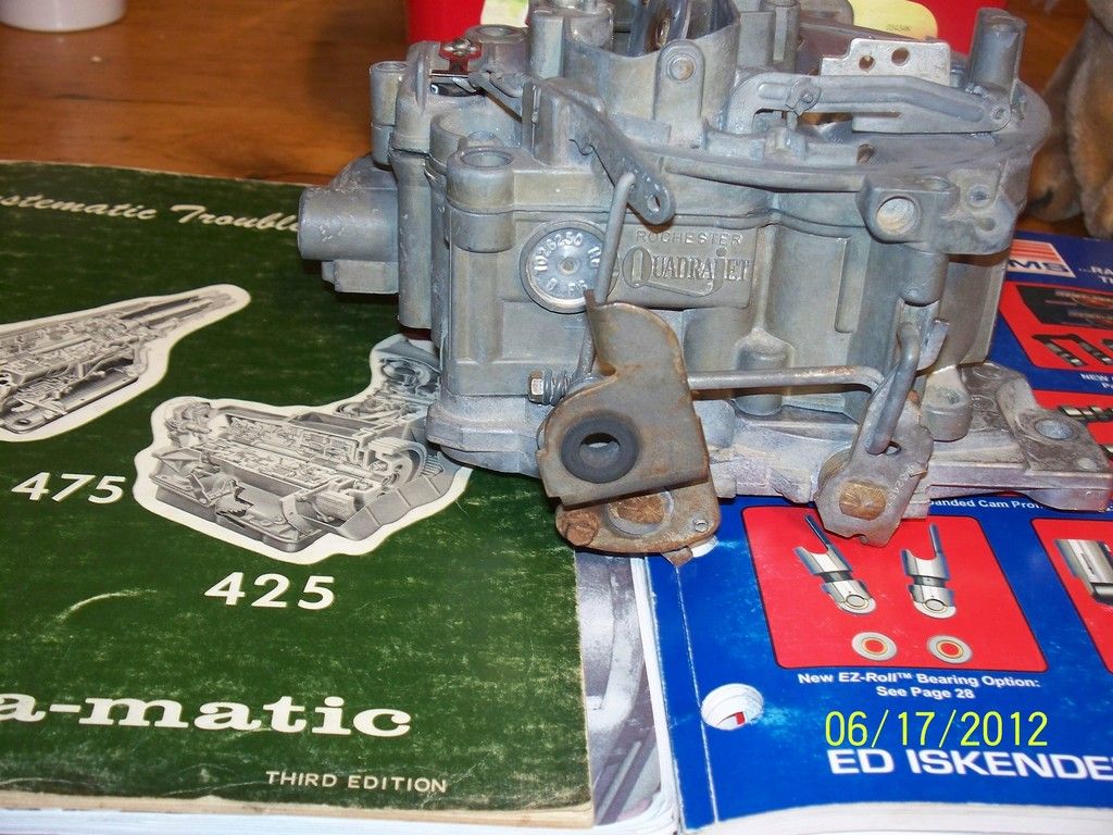
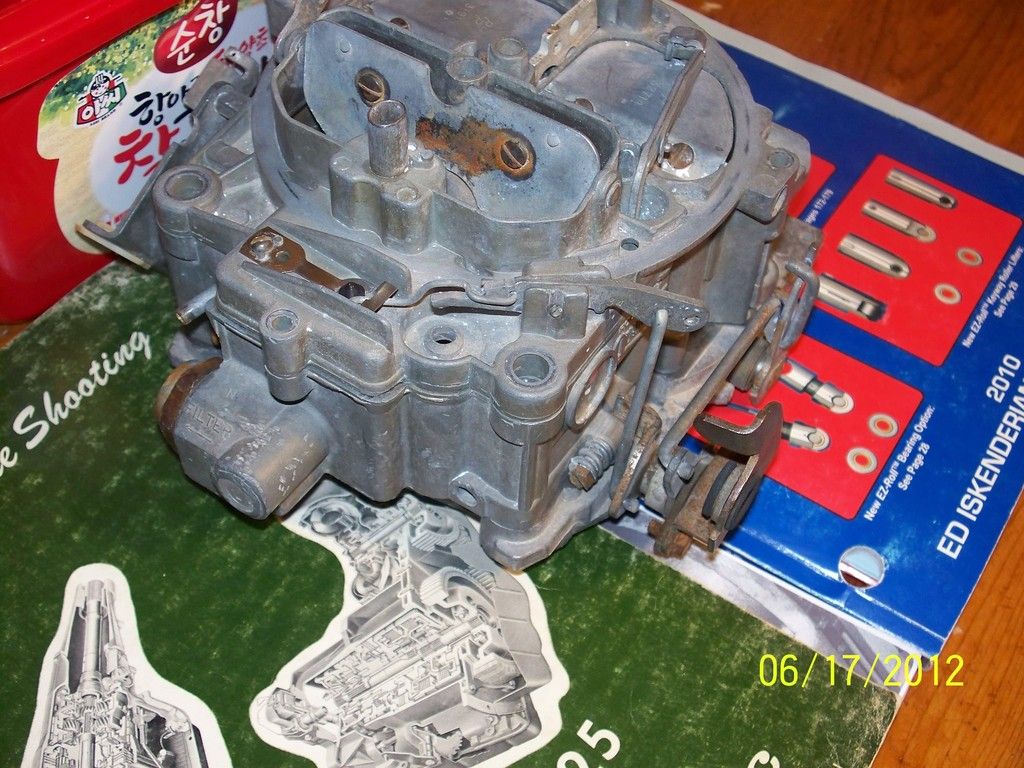
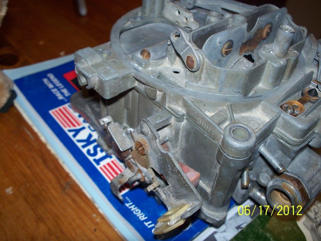
Quadrajet Info by Lars

207K views 27 replies 9 participants last post by  corvettejunkie666 
#1 ·
With permission by the author.


Technical Information Bulletin Rev F 4-5-05
Q-Jet Problems I have Seen

by Lars Grimsrud
Lafayette, CO

Missing Fuel Filter
Results in: Lack of a fuel filter will allow dirt and debris to get into the carb. This often unseats the needle, resulting in severe carb flooding. I have also seen this cause severe sediment build-up in the float bowl, with eventual plugging of metering orifices, resulting in poor idle and other performance problems such as jammed power piston.
Comments: A lot of Q-Jets have had their filters removed. People seem to think that the little filter in the carb must be very restrictive to fuel flow, so they toss it and install an in-line filter. Eventually, somebody removes the in-line filter, but never puts the in-carb filter back in. The in-carb filter is actually very good, and does not produce a flow restriction that will hamper a street-driven performance vehicle.

Missing Fuel Filter Spring
Results in: A missing filter spring will allow dirt to completely bypass the filter. Results in same problems as a missing fuel filter.
Comments: These springs are commonly lost during filter changes. Many people don’t see a purpose in the spring, so they leave them out. I’ve also heard people say that the spring makes the filter “block off” fuel flow, so they remove it. The spring is essential for proper filter operation.

Stripped Fuel Inlet Threads
Results in: Inability to tighten the inlet fitting with resulting fuel dripping/leaking onto the intake manifold.
Comments: Very common on the pre-’75 carbs with the smaller diameter inlet fittings. I’ve seen people try to epoxy the fittings in place. This never works. There are also over-sized self-tapping fittings available that can solve the problem temporarily, but these fittings will also strip out. There are O-Ring type adapters that can be used to seal up the inlet system, but these fittings do not allow use of the in-carb fuel filter. The only way to properly repair this problem is to have the inlet machined and tapped for a HeliCoil thread insert.

Damaged or Broken Fuel Inlet Fitting
Results in: Fuel leaking at carb inlet. Fitting cannot be tightened enough to stop leakage.
Comments: It is actually possible for the big 1” Hex fitting at the carb inlet to break internally. The cone-shaped inner seal surface breaks loose from the wall of the fitting, making the fitting appear to be a 2-piece assembly. It is also common for the cone-shaped inner seaing surface to be gouged, scratched, or damaged, making it impossible for the flared tube end to seal against it. Replace this fitting if there is any damage.

Missing Inlet Fitting Seal
Results in: Fuel leaking at carb inlet. Fitting cannot be tightened enough to stop leakage.
Comments: The early Q-Jets use a black, rubber-coated metal seal ring up against the hex nut part of the big inlet fitting as a fitting seal. Later Q-Jets use a white plastic seal ring at the end of the fitting threads as a fitting seal. These seals – not the fitting threads – seal the fitting. There is no point in using Teflon Pipe Tape on the threads to seal the fitting if these seals are missing.

Stripped Inlet Seat Threads
Results in: A loose/stripped seat in the float bowl will allow fuel to leak by the needle/seat assembly. Mild to severe flooding can result. Poor idle. Poor hot-start.
Comments: Degradation and stripping of the seat threads is common in the older Q-Jets – especially the ones that have been commercially rebuilt and sandblasted. I often see carbs with the seat epoxied into the stripped out float bowl. Epoxy will not hold the seat in the bowl for very long. The problem can only be fixed by machining and tapping the seat inlet threads for a HeliCoil insert.

Damaged/Leaking Needle/Seat
Results in: Mild to severe flooding and rich-running conditions. Poor idle. Idle mixture screws will be non-responsive. Hard to hot-start.
Comments: It doesn’t take much to cause enough damage to a needle/seat assembly to make it leak: A piece of debris passing through or damaged caused during a previous rebuild process can easily make the assembly leak. Replace the assembly anytime the carb exhibits flooding or fuel control problems.

Needle Retaining Clip Incorrectly Installed to Float Arm
Results in: Flooding, poor idle, poor hot-start, fuel puddling in bottom of intake after shut-down.
Comments: This is one of the most common assembly problems I see on Q-Jets. GM actually issued a Service Bulletin on this subject back in the late ‘60s because GM technicians were doing the same mistake. There is a small retaining wire on the needle. The float arm has two holes in it where the needle interfaces. People think the retainer goes through the float arm holes. Fact is, the retainer slips over the rear edge of the float arm, and must not be installed through the holes. Installing the retainer through the float arm holes results in the needle and/or float jamming.

Float Level Too Low
Results in: Hesitations, sluggish performance, poor idle mixture screw response, surging at cruise, “flat” feeling going to wide open throttle.
Comments: Different year Q-Jets have different float level requirements. The early carbs all have a factory spec of ¼”. The late carbs have much lower specs at about .420”. Setting up an early carb to the late spec is a common mistake, and will cause performance problems. Personally, I prefer setting up the early carbs to a float level of .300” to .375”. I run the late model carbs at .400” - .420”.

Float Level Too High
Results in: Flooding, fuel coming out of accelerator pump shaft hole, leaking air horn gasket, fuel discharging out main discharge nozzles at idle, fuel dribbling down venturi after engine shut-down, poor hot-start, hesitations off idle, poor fuel economy.
Comments: See comments above for Float Level Too Low. Often, late model carbs are set up to early model specs. This results in poor performance on the post-’75 carbs.

Incorrect Float Installed
Results in: Flooding, fuel coming out of accelerator pump shaft hole, leaking air horn gasket, fuel discharging out main discharge nozzles at idle, fuel dribbling down venturi after engine shut-down, poor hot-start, hesitations off idle, poor fuel economy.
Comments: Over the years, several different floats were used on the Q-Jets. These floats had different geometry with differing float arm lengths and different float lengths. Some floats can be interchanged, but this will result in binding, sticking and improper needle control. I also see a lot of aftermarket brass floats used in Q-Jets. The original carbs came from the factory with NitroFill floats. Brass floats do not behave the same. Be sure to install a correct NitroFill float when you work on these carbs. Echlin makes an exact reproduction and correct replacement float.

Fuel-Logged Float
Results in: Flooding, fuel coming out of accelerator pump shaft hole, leaking air horn gasket, fuel discharging out main discharge nozzles at idle, fuel dribbling down venturi after engine shut-down, poor hot-start, hesitations off idle, poor fuel economy.
Comments: Older NitroFill floats can actually become fuel soaked and start to float lower than intended. This has the same effect as raising the float level. Replace the float any time you rebuild the carb.

Float Binding Against Power Piston Tower
Results in: Flooding, fuel coming out of accelerator pump shaft hole, leaking air horn gasket, fuel discharging out main discharge nozzles at idle, fuel dribbling down venturi after engine shut-down, poor hot-start, hesitations off idle, poor fuel economy.
Comments: During rebuilding, it is easy to bump and bend the arms on the float. If the arms are squeezed together, the float arms can rub against the power piston tower, and this will restrict float movement. In severe conditions, it will prevent the needle from ever seating, resulting in severe flooding. It is also possible to bend the float arms such that the float itself rubs against the walls of the float bowl. This causes the same problem.

Incorrect Main Jets
Results in: Hesitations, sags, poor performance, ineffective idle mixture screws, poor idle, surging, poor mileage, poor vacuum, sooting out the tailpipes, poor starting characteristics, stumbles, poor WOT power.
Comments: “Creatively jetted” Q-Jets are more the norm than the exception. Be sure you know the stock and correct jetting configuration for your carb before you ever begin chasing problems. Always start with the correct stock jetting setup before you start tuning, and keep changes conservative: The boys and girls who designed these things in Detroit put a lot of work into the jetting configuration on these carbs, and they actually knew what they were doing…

Incorrect Primary Metering Rods
Results in: Poor idle, rich idle, ineffective idle mixture screws, surging at cruise, poor mileage, poor cold-running characteristics, hesitations off idle and/or at cruise, poor manifold vacuum with resultant ancillary problems.
Comments: In addition to seeing incorrectly sized metering rods for the application, I am also seeing carbs with the WRONG rods installed. Pre-’75 (up through ’74) Q-Jets use metering rods that are approximately 2.47” long overall (total length from the metering tip to the extreme top of the rod). 1975 and newer Q-Jets use rods that are about 2.40” long. The early rods typically also have just a plain number stamped into them (like, “44”), or will often have the letter “B” after the number (like, “44B”). The later rods will often have the letter “K” or “M” after the number. If an early rod (long rod) is installed in a post-’75 carb, the actual shank (body) of the rod will be stuffed down into the jet, resulting in a severe lean condition with associated marginal drivability. Likewise, if a late rod is used in an early carb, there will be virtually no lean-out from the power piston at idle or cruise, and the carb will suffer a severe rich-running condition.

Incorrect Secondary Metering Rods
Results in: Poor WOT performance, sags or flat spots going into the secondary side, car “falling on its face” somewhere in the secondary range, smoke at WOT.
Comments: Since the secondary rods are so easy to change, they are frequently used as the “primary tuning tool” on a Q-Jet. This results in some pretty strange rods being installed. Make sure you know which rods are stock for your application, and make changes in small increments from there.

Incorrect Power Piston Spring
Results in: Poor idle, rich idle, ineffective idle mixture screws, hesitations and stumbles.
Comments: At some time, there must have been a popular article published that told people to cut their power piston springs to hop up their Q-Jet: I see more cut springs that you can imagine. A cut, or soft, spring will keep the power piston seated in the full lean position during part-throttle power, resulting in a sag and poor throttle “feel” during part-throttle acceleration. In contrast, if a stiff spring has been installed, the piston will never seat, and the carb will be running in a full-rich condition even at idle. This causes incredible tuning problems for idle and off-idle performance, and the idle mixture screws will have little effect. New power piston springs are available in packs of 10. If you suspect the spring to be non-original, stick in a new one to eliminate this as a problem.

Jammed Power Piston
Results in: Poor idle, rich idle, ineffective idle mixture screws, hesitations and stumbles.
Comments: The power piston can be jammed in either the full lean or full rich position, producing the same symptoms as an incorrect spring. You can test the power piston with the engine “off” by inserting a thin, long screwdriver down the bowl vent in the air horn. You should be able to depress the power piston and feel it pop back up. A jammed piston is usually caused by dirt entering the bowl, but can also be caused by carbon sooting up through the intake manifold from bad valves or valve timing problems.

Bent Primary Metering Rod Hanger Arms
Results in: Flooding, poor idle, hesitations, poor throttle response, poor fuel economy, ineffective idle mixture screws, sooting out the tailpipe, plug fouling.
Comments: If the primary metering rods were not engaged properly into the main jets before the air horn was installed to the fuel bowl, the rods will bend and this will also bend the piston hanger arms. If the arms are not bent back to their correct and original position, the primary metering rods will be pulled up out of the jets into the full-rich position, if they engage in the jets at all.

Bent Primary Metering Rods
Results in: Flooding, poor idle, hesitations, poor throttle response, poor fuel economy, ineffective idle mixture screws, sooting out the tailpipe, plug fouling.
Comments: If the primary metering rods were not engaged properly into the main jets before the air horn was installed to the fuel bowl, the rods will bend and fail to engage into the main jets. This causes a severe rich condition.

Cut Power Piston Lower Stop Pin
Results in: Hesitations, stumbles, poor idle, surging at cruise, ineffective idle mixture screws, hot running.
Comments: Many (not all) Q-Jets have a lower stop pin in the power piston. This pin rests against a cam in the throttle plate, and determines the lowest (leanest) position for the power piston. Cutting this pin results in the primary metering rods seating too deeply into the main jets, severely restricting fuel flow. Again, there must have been an article published at some time telling people to do this…

Incorrectly Set Power Piston Stop Height
Results in: Poor idle, rich idle, ineffective idle mixture screws, hesitations and stumbles.
Comments: Post-’75 Q-Jets have an easily adjustable power piston stop that determines the lowest (leanest) position of the piston. Raising or lowering this stop outside its limits will adversely affect all performance parameters of the power enrichment circuit. Pre-’75 Q-Jets also have an adjustable stop hidden under a steel cap in the forward side of the lower throttle plate.

Incorrectly Adjusted Secondary Rod Hanger Height
Results in: Lean secondary performance, flat spot going into the secondaries, poor WOT power.
Comments: It is common for the secondary rod hanger to not pull the rods up out of the metering holes adequately. This produces a lean condition with associated poor power. The distance from the top of the choke rear airhorn wall to the center of the rod holes with the secondary airvalve in the wide open position should be 41/64”.

Incorrectly Adjusted Secondary Airvalve
Results in: Car falls on its face when the gas pedal is pushed to the floor, sag going into the secondaries, flat spot going into the secondaries, jerk or delay going into the secondaries.
Comments: Very common problem. The secondary airvalve is adjusted using the slotted head screw at the secondary airvalve lever, and this is released using the allen head screw up underneath the airhorn. Spring windup should be ½ to ¾ turn.

Jammed secondary airvalve
Results in: Poor WOT power and performance, car falls on its face going into the secondaries, flooding going into the secondaries.
Comments: It is a common problem on the Q-Jet for the two back screws in the airhorn to have been tightened so much that the airhorn is distorted in this area. This distortion will jam the secondary airvalves, preventing them from opening. When the secondary throttle plates are mechanically opened (pushing the gas pedal to WOT) and the airvalve is jammed closed, manifold vacuum will suck fuel right out of the secondary discharge nozzles with no airflow going through the secondary side. To fix this, the carb must be removed, and the displaced metal must be filed away. Often, the secondary airvalve plates must be loosened and re-aligned to assure a bind-free operation.

Incorrect, Missing or Damaged Secondary Airvalve Rod
Results in: Car falls on its face when the gas pedal is pushed to the floor, sag going into the secondaries, flat spot going into the secondaries, jerk or delay going into the secondaries, flooding during cold-start, erratic fast idle.
Comments: The secondary airvalve rod is one of the most misunderstood parts on a Q-Jet carb. Owners see that the rod is holding the secondary airvalve closed when the engine is running, so the rod is either removed or bent. The next guy who builds the carb installs an incorrect rod, which really screws up the secondary airvalve operation. On early Q-Jets, this rod also operates the choke vacuum break system, so removal or bending of the rod prevents the choke from cracking open during cold-start. This causes flooding and rich running in cold weather operations.

Cracked or Warped Air Horn
Results in: Fuel leaking around air horn gasket, poor idle, ineffective idle mixture screws, erratic idle, fuel discharging out main discharge nozzles at idle, hesitations & stumbles, poor throttle response.
Comments: Very common on older Q-Jets: The two forward carb hold-down bolts have been tightened so tight that the entire top of the carb is warped or cracked. Once this happens, the airhorn no longer seals properly to the float bowl of the carb. This causes leaks in the idle transfer fuel circuit between the airhorn and the bowl, effectively eliminating the entire idle circuit in the carb. It also causes the gasket to be ineffective in sealing the rest of the airhorn to the bowl, resulting in fuel leakage around the top of the carb. No fix for this – buy a new carb.

Wrong Air Horn Gasket
Results in: Poor idle, ineffective idle mixture screws, erratic idle, fuel discharging out main discharge nozzles at idle, hesitations & stumbles, poor throttle response.
Comments: Use of the incorrect airhorn gasket can result in blockage of idle bleed air passage and blockage of idle fuel passages between the float bowl and the airhorn. There are several styles of airhorn gaskets, and many of them look very similar. It’s a good idea to lay the airhorn gasket you’re going to use onto the float bowl and visually verify that all the holes line up.

Wrong Carb Major Component Parts
Results in: Bizzare performance and drivability problems.
Comments: As “numbers matching” carbs are becoming older, worn out, and more rare, people are doing some very strange things with mixing and matching components. I’ve seen many cases of “correct” Q-Jets (the carb has the right number stamed into the side of the float bowl) with air horns and throttle plates scavenged from completely different makes and model carbs. The last one I saw was a 1972 454 4-speed Vette carb (based on the number) with a 1971 Pontiac airhorn and a 1968 Impala throttle plate. Every single component in the carb, except for the float bowl itself, was incorrect and unusable. If you’re buying carbs at swap meets and on eBay, make sure you know how to visually identify the carb you’re after.

Plugged accelerator pump transfer holes in air horn
Results in: Off-idle stumble or hesitation, hard cold-start.
Comments: There is a tiny transfer hole that runs horizontally in the air horn, just inside of the actual accelerator pump discharge orifice. It is common for this to be plugged with some type of debris, especially in carbs that have been sitting around for a while. If this passage is plugged, there will not be any accelerator pump shot.

Jammed accelerator pump check ball
Results in: Off-idle stumble or hesitation, hard cold-start.
Comments: This is a common problem in carbs that have been allowed to “dry out” for a while. Sediment in the bottom of the fuel bowl will lock up the check ball as if it were set in concrete. This will prevent any accelerator pump discharge.

Accelerator Pump Rod Installed in Wrong Hole in Pump Arm
Results in: Off-idle stumble or hesitation.
Comments: There are two holes in the accelerator pump lever arm for the lever arm rod to engage into: Inner and Outer. The outer hole produces a leaner pump shot, and can cause a lean stumble on engines requiring a robust pump shot. Corvettes and performance cars always used the rich, inner pump arm hole.

Jammed accelerator pump
Results in: Off-idle stumble or hesitation, hard cold-start.
Comments: This is becoming a common problem. The alcohol additives in modern fuels are not compatible with the materials used in many accelerator pumps (even some of the pumps in brand new carb kits). This causes the pump plungers to swell up and to seize in the pump bore. The spring on the pump shaft still allows the shaft to move up and down, making it look as if the pump is functioning. But the pump itself can be seized up solid in the bore with the shaft working just fine. To fix this, you must install a pump that is specifically compatible with alcohol.

Worn accelerator pump
Results in: Off-idle stumble or hesitation, hard cold-start.
Comments: Common on older carbs and on carbs that have been allowed to dry out (vehicles stored without being started through the entire winter season). The rubber plunger material will dry out and shrivel up, making the accelerator pump completely ineffective. The pump must be replaced.

Missing idle bleed restrictors
Results in: Poor idle, ineffective idle mixture screws, off-idle hesitations, very high idle required to keep engine from dying when placed in “drive,” fuel discharging out main discharge nozzles at idle.
Comments: Different Q-Jets have different idle bleed calibrations. Part of this calibration is the installation of some brass restrictor orifices in the venturi area/booster ring area. Many commercial rebuilders will actually remove the orifices during rebuild, causing too much air to be pulled into the idle fuel circuit. The engine will then only idle if the idle speed is run up into the transition & cruise metering circuit. This is a difficult problem to diagnose and correct, since some Q-Jets did not use the restrictors, and replacement restrictors are not serviced separately.

Emulsion tubes fallen out of air horn and laying in float bowl
Results in: Poor idle, hesitations, odd & inefficient performance.
Comments: It is very common on older and high-mileage Q-Jets for the air horn emulsion tubes to fall out and end up in the bottom of the float bowl. These tubes assist in the emulsifying of the fuel mixture, and will cause a notable decrease in carb performance when they fall out. They can be re-installed into the air horn and tapped into their fully-seated position with a small plastic mallet.

Plugged idle air bleed transfer holes in float bowl
Results in: Poor idle, idle mixture screws ineffective, fuel discharging out main discharge nozzles at idle, erratic idle, high idle required to keep engine running (engine dies when idle speed is decreased).
Comments: The Q-Jet has supplementary idle air bleed holes in the throttle plate just below the primary butterfly plates. These bleed holes assure that the engine is allowed to pull enough air at idle to keep it running, while keeping the throttle plates closed far enough to keep fuel discharging through the idle metering circuit. The bleed holes act like the “drilling holes in the butterflies” trick that so many people advocate. The air for these holes is transferred from the venturi area of the carb through two small holes in the outer plenums of the float bowl. For some reason, it is very common for commercial carb builders to plug these transfer holes with aluminum plugs or rivets. This dramatically changes the idle characteristics of the carb, and frequently destroys the entire idle and cruise mixture control. If you see these plugs installed, drill them out and set up your carb the way it should be.

Leaking well plugs
Results in: Hard starting after the car has been sitting for a day or two. Flooding and black smoke when hot-starting.
Comments: This is a grossly over-rated problem. It is not by far as common as some articles and publications would have you believe. The Q-Jet uses soft metal plugs to seal off the production drill passages in the bottom of the float bowl. The passages are drilled and plugged under the main metering jets and under the secondary metering orifices, usually referred to as the primary and secondary well plugs. The primary well plugs are visible from the bottom of a fully assembled carb. The secondary well plugs are only visible and accessible once the throttle plate is removed from the float bowl. If these plugs leak, the float bowl will run empty after sitting overnight, and all the fuel will end up inside the intake manifold. You can test for this condition by simply removing the carb, filling the float bowl with fuel, and observing the plugs to see if they leak. It would be a rare condition if you actually have a leaker. But if the primary plugs leak, the only permanent solution to the problem is to drill the plugs out, tap the passages for a #10-32 screw, and install a ¼” long allen-head countersunk screw with some good epoxy into each of the two passages. I see carbs with the plugs coated with epoxy: Simply smearing some epoxy onto the well plugs will not seal them permanently. You have to drill, tap, and plug them with the epoxied screws if you want the repair to last. The secondary well plugs can be sealed by using the seal gasket supplied in all of the Echlin brand carb kits.

Porous Float Bowl Casting
Results in: Hard hot-starts due to fuel leaking into the intake manifold. Hard cold-starts due to empty float bowl. Rich idle. Ineffective idle mixture screws.
Comments: This is one of the more bizarre problems I have encountered, but I’ve seen several. Very difficult to detect if you’re just doing a quickie rebuild and slapping a carb kit in the carb, since nothing appears to be wrong. With a porous casting, fuel can not only leak through the bottom of the float bowl, but fuel can leak between the vertical fuel transfer passages that run up the forward sides of the venturis. This will cause main metering fuel to dump out the transfer fuel slots in the throttle plate. To test for a porous casting, strip the carb down to the bare float bowl. Install the needle and the seat to seal off the fuel inlet. Then, pour any type of solvent (lacquer thinner) into the float bowl and fill it to within 3/8” of the top of the bowl. Let it sit for a few minutes. Then, without allowing the solvent to spill, raise the float bowl so you can inspect the bottom of the bowl for any seepage or leaks. There should be no wet spot or drips at all coming from anyplace on the float bowl. Accessible porous spots can be cleaned up and sealed with JB Weld.

Undrilled Passages
Results in: Unexplainable fuel metering problems, either running too rich or too lean in one or more modes of operation, and normal jetting corrections will not fix it.
Comments: Another one of those odd, rare problems, but they do occur. I have seen several carbs that have had fuel and vacuum transfer holes missing from the factory – the holes will be partially drilled, with evidence that the tooling drill bit broke during the operation. These carbs have run poorly since the car was built, and often these carbs will have some very strange jetting combinations and setups due to somebody trying to tune the carb without realizing that a hole was missing.
The most common undrilled hole is the power piston vacuum passage in the throttle plate on 1975 – 1980 Q-Jets. This hole was drilled in 2 operations: halfway through the throttle plate from the top, and then at a 45-degree angle up from the bottom to intersect the top hole. When this hole is missing, the power piston stays in the full rich condition at all times, causing horrible idle problems.
The second most common undrilled passage is the ported vacuum pickup hole in the 1968-1971 carbs. Many of these carbs have a throttle plate that has no hole for the ported vacuum source, resulting in the ported vacuum nipple on the forward passenger side of the carb being a plugged, dead end port. Since most stock vacuum advance systems run off this port, the undrilled passage results in no distributor vacuum advance with associated poor mileage and poor throttle response at cruise. To test for this condition, simply attach a vacuum hose to the nipple and blow in it: you should be able to blow through the hose. If not, you need to drill the hole in the throttle plate.
When building a Q-Jet, I like to use the little red plastic nozzle tube that comes with every can of WD40 and blow a wad of WD through each passage. I also trace out the passages as they connect from the float bowl to the throttle plate to make sure they form a complete circuit. Doing this is actually fun for the novice, since you gain a very good understanding of the carb operation when you spend 10 minutes tracing out the passages.

Eroded or Mismatched Secondary Fuel Passages
Results in: Massive bog when going into the secondaries. Vehicle falls on its face, and may backfire up through the carb.
Many of the commercially rebuilt carbs get sandblasted by the rebuilders, and assembled using various parts and components from various different carbs. This can result in 2 conditions preventing secondary fuel flow:
First, the top of the float bowl casting in the secondary fuel passage area (the two big holes in the casting coming up just at the back wall of the float bowl, forward of the secondary venturies) get eroded and worn down by the sandblast process. When this happens, the top surface of these transfer hole passages will not seal tightly against the mating passages in the airhorn (the “top” of the car). When the secondaries open up and attempt to siphon secondary fuel out of the secondary discharge tubes (the two tubes sticking out at an angle out of the airhorn under the airvalves), nothing but air is siphoned through this leak.
Second similar problem occurs when an airhorn from one carb is used on the float bowl from another carb: If the warpage in the airhorn does not match the warpage of the float bowl, there can be an airgap between the two components in this critical transfer passage area.

HeliCoiled Main Metering Jet Holes
Results in: Rich running carb throughout the operating range.
Many commercial rebuilders will attempt to save a stripped out float bowl casting by installing a HeliCoil in the main jet holes. When drilling and tapping for the HeliCoil, the counterbored sealing surface for the jet is removed, and the main jets can no longer seal around their perimeter: fuel will leak down around the outside of the jets as well as being metered through the center of the jets. A carb float bowl with a stripped or HeliCoiled main jet hole cannot be saved - it goes in the trash can.

Wrong throttle plate gasket
Results in: Poor idle, erratic idle, ineffective idle mixture screws, symptoms of a vacuum leak.
Comments: There are several different designs for the throttle plate gasket, and they do not interchange. Two common problems occur: The first problem was addressed in a GM Service Bulletin around 1971. There is a difference in the open area in the gaskets just forward of the centerline of the primary throttle holes. Some later carbs use a gasket with a larger open hole in this area. If this gasket is used on an earlier carb, you will end up with a massive, undetectable vacuum leak. The other problems with these gaskets occur due to the idle fuel and vacuum bleed holes not lining up from one design to the next. Use of the incorrect gasket can result in blocked idle fuel and blocked vacuum signals. Always lay the gasket onto the float bowl and onto the throttle plate to check the hole alignments.
Another odd twist to these gasket designs occurred in the late ‘80s. We are seeing more and more late ‘80s truck Q-Jets (non-ECM carbs) being used on musclecars, so the problems are becoming more frequent: In the late ‘80s, there is a fuel discharge hole drilled from the secondary fuel well to a small hole located between the secondary throttle holes in the base of the float bowl. Carbs with the fuel hole require use of a gasket that has NO HOLE at this location. If a standard late ‘70s or early ‘80s gasket is used with this carb, manifold vacuum will siphon fuel right out of the secondary side of the carb, discharging the fuel right out of the power brake vacuum hole location in the bottom of the carb throttle plate. You will have a massive rich-running condition, even with the idle screws completely closed (blocking all primary fuel flow) and with no evidence of fuel being discharged on the primary side.

Loose throttle plate
Results in: Erratic idle, poor idle mixture screw response, off-idle hesitations, symptoms of a vacuum leak.
Comments: Since the throttle plate attach screws are located in the bottom of the carb, you cannot tell that the screws are loose until the carb is removed from the engine. It is quite common for the screws to be loose, producing not only a vacuum leak around the base of the fuel bowl, but violating the seal for the idle fuel transfer passages. This makes adjustment of the idle mixture and idle speed almost impossible.

Wrong idle mixture screws
Results in: Poor idle screw mixture response, poor idle, erratic idle.
Comments: There have been several styles of idle mixture screws used in the Q-Jets over the years. The screws differ in the taper of their tips: Some screws have a steep taper, while others are very long and slender. Commercial rebuilders typically remove the nice factory screws and install aftermarket one-size-fits-all steep-taper screws. These steep-taper screws often do not work at all in many Q-Jets. Most of these steep-taper screws are brass. All factory Q-Jet idle mixture screws are steel. If you have a set of brass idle mixture screws in your carb, trash them and find a correct set of factory screws.

Seized/rusted idle mixture screws
Results in: Adjustment of idle mixture not possible.
Comments: A lot of the cars used in the Midwestern and Coastal States have severe corrosion problems, as we know. The steel mixture screws in the aluminum throttle plate promote dissimilar metals corrosion, and can often seize solid into the throttle plate. Attempts to force them out will usually result in the screws snapping off in the throttle plate, rendering the carb useless. To remove rusted and seized mixture screws, the throttle plate must be removed from the carb, and the screws must be carefully heated while “rocking” them back and forth to loosen them up.

Seized/rusted fast idle screw & cam
Results in: Adjustment of fast idle not possible.
Comments: The same cars with the rusted and seized idle mixture screws will quite often also have rusted & seized fast idle screws and idle cams. Once again, any attempt to force the fast idle screw will usually result in the screw snapping off in the fast idle lever. To remove rusted and seized fast idle screws, the throttle plate must be removed from the carb, and the screw must be carefully heated while “rocking” it back and forth to loosen it up. To loosen the cam, the throttle shaft cam screw must be carefully removed, and the spring & linkage pieces must be carefully pried loose, cleaned up, and re-assembled.

Primary throttles adjusted to not open fully
Results in: Poor throttle response, poor WOT performance.
Comments: It is amazing how common it is for the throttle linkage on the carb to be grossly misadjusted. When rebuilding a carb, always operate the throttle linkage and make sure the primary throttles open fully. They should open the the exact vertical position. Anything less will prevent full airflow through the carb. The position of the blades is adjusted by bending the throttle stop linkage.

Primary throttles adjusted to open over-center
Results in: Poor WOT performance.
Comments: Even more common that throttles that do not open fully are throttles that have been adjusted to open over-center. I guess people figure that te car will run faster if you can open the throttle even more. Fact is, once the throttle blades go over-center, they are restriction airflow just as bad as a throttle that does not open fully. Check for an over-center condition anytime you rebuild you carb, and bend the linkage so that the throttles stop at the vertical positioon.

Secondary throttles adjusted to not open fully
Results in: Poor WOT performance.
Comments: The secondary throttle shaft is actuated by a link off the primary shaft that hits a lever on the secondary throttle shaft. It is common for this to be misadjusted so that the secondary throttle blades do not fully open. Some factory cars & carbs were intentionally set up to limit secondary throttle opening (like 1st-generation 400-powered Firebirds) in order to limit horsepower for one reason or another. Check for this whenever the carb is disassembled and adjust it by bending the contact tang on the primary throttle shaft.

Secondary throttles adjusted to open over-center
Results in: Bog or hesitation going into the secondaries, poor WOT performance.
More common that secondaries that do not open fully are secondaries that open too far. Q-Jet secondary throttle plates should NOT open to the full vertical position or beyond. The secondary throttle plates should open to a position where the angle of the throttle plates points and aligns towards the lower edge of the secondary airflow baffle located in the secondary venturi bore. When the secondary throttle plates are opened beyond this point, turbulence in the secondary side actually decreases airflow. Also, if the secondary throttle plates are adjusted to open over-center, they will, as a result, also open too soon. This will cause a stumble or hesitation going into the secondaries. Adjust and align the opening by bending the primary throttle contact tang.

Secondary throttles not closing – not aligned in bores
Results in: Fuel discharging out the secondary discharge nozzles at idle & cruise, poor idle, flooding, black smoke, off-idle stumble.
Comments: If the secondary throttle plates do not fully close, or if they are misaligned in their bores, engine vacuum will be applied to the secondary venturi area. With engine vacuum in the veturi area, and the upper airvalves closed, fuel will be siphoned out of the secondary discharge nozzles. This will cause a very rich idle and cruise condition. The problem can be caused by the secondary throttle linkage being bent/misadjusted, or by the secondary butterflies being misaligned in the throttle plate bores.

Secondary throttle linkage springs missing or incorrectly installed
Results in: Secondary throttles not closing (see above), secondary throttles inoperative.
Comments: There is no reason to disassemble and remove the secondary throttle shafts, throttle plates, and the associated springs during a rebuild, but some people do it anyway. During re-assembly, these parts get left out or incorrectly assembled, resulting in the secondary throttle plates not closing fully or no longer actuating at all. These problems can be hard to identify unless you are very familiar with the Q-Jet or unless you have another carb to compare against.

Missing secondary airflow baffle
Results in: Poor secondary WOT performance, sags or hesitations at WOT.
Comments: The baffle installed inside the secondary venturi area actually creates the venturi effect required to discharge the fuel properly out of the secondary discharge nozzles. Deleting the baffle causes turbulence in the secondary venturies that will completely mess up your secondary metering. Make sure the baffle is correctly in position. It is frequently missing.

Choke plate misaligned
Results in: Poor cold-running characteristics, sticking choke, engine stalling when cold, engine not coming down off fast idle unless gas pedal is hit.
Comments: If the choke plate is misaligned in the airhorn, the choke can stick and bind in a part-closed position. It cam also fail to close completely during initial cold-start. Check to make sure the plate fits squarely and tightly in the air horn. If not, crack the two screws loose and wiggle the plate around until it fits right.

Choke pulloff seized or ruptured
Results in: Poor cold-run characteristics, flooding when cold, stalling when cold, poor fast idle control, sag or hesitation going into the secondaries.
Comments: This is one of the most common maladies on older Q-Jets. When the pulloff fails, not only do you loose proper control over the choke, but you also loose opening rate control over the secondary airvalve. Always check the pulloff by attaching a long piece of vacuum hose to it and sucking on it. The pulloff should smoothly retract, and it should smoothly extend when the suction is released.

Choke pulloff incorrectly adjusted
Results in: Poor cold-run characteristics, stalling when cold, flooding when cold, engine won’t stay running after cold start-up.
Comments: The primary purpose of the choke pulloff is to crack the choke open just a tad upon initial cold-start. If the choke is not cracked open, the engine will flood. If the choke is cracked open to far, the engine will lean out and stall. When correctly adjusted, the choke pulloff will open the choke ¼” as measured from the forward lower edge of the choke plate to the airhorn wall.

Fast idle screw incorrectly adjusted
Results in: Initial cold-startfast idle too high or too low.
Comments: The fast idle screw is hidden so well that many people don’t know it even exists. The screw is located under the choke linkage on the passenger side of the car. The screw head faces forward. Fast idle speed should be adjusted to about 1200 rpm on a cold engine.

Choke linkage/intermediate shaft system incorrectly assembled or missing pieces
Results in: Inoperable choke, engine not coming down off fast idle, sticky choke.
Comments: The choke and fast idle linkage on a Q-Jet can be a mystery of odd parts once the carb is fully disassembled. It is easy to get some of the pieces incorrectly assembled or installed in a bind. When this happens, the choke system will not operate properly. Best to take a look at another carb and do a little comparison if you’re not intimately familiar with the linkage system.

Broken choke housing
Results in: Poor choke performance, inoperable choke, vacuum leak.
Comments: The 1975 and newer Q-Jets use a cast aluminum choke housing for either a hot air choke or for an electric choke. Many carb kits contain new choke hosing screws, and these screws are often too big for the intended application. Installation of the aftermarket screws will crack the choke housing, and can make it impossible to properly adjust the choke cover. The hot air chokes have a vacuum source from the inside of the choke cover to draw hot air through the choke system. If the housing is cracked from the oversized screws, and the choke cover is not tightly installed, the vacuum source will not pull the hot air through the system properly, and the choke will remain “on” too long. Broken housings can be welded.

Missing choke intermediate shaft seals
Results in: Sticky choke operation due to dirt contamination.
Comments: The 1975 and newer Q-Jets use two shaft seals on the choke intermediate shaft: One seal is installed inside the choke housing, and the other seal is installed in the carb float bowl where the shaft goes through the side of the bowl. Failure to install the seals can result in a sticky choke system.

Missing secondary lockout lever
Results in: Bogging, sag or stumble when going to WOT with a cold engine. Engine damage from going to WOT on a cold engine.
Comments: The secondary lockout lever, located on the passenger side of the carb just forward of the secondary throttle shaft, is intended to prevent the secondaries from opening when the engine is cold. Placing the engine under maximum load before reaching normal operating temperature can result in engine damage. The lever is retracted by the choke linkage as the choke opens up. Many people are afraid that the lockout lever is preventing the secondaries from opening, so they remove the lever. This is fine on a racecar, but not advisable on a street car. Make sure your choke is operating, and make sure the lever is adjusted correctly to perform its intended function. When properly adjusted it will retract when the engine has warmed up, and the secondaries will function as intended.

Incorrectly adjusted secondary lockout lever
Results in: Inoperable secondaries.
Comments: It is possible to have the lockout lever and the secondary throttle shaft pin adjusted so that the secondary throttles remain locked out even after engine warm-up. Check the lockout lever once the choke is wide open and assure that the lever does not interfere with throttle opening.

Missing idle vent parts
Results in: Dirt & debris entering the float bowl.
Comments: The early Q-Jets use an idle vent valve on the forward, upper part of the carb. The idle vent valve consists of two stainless steel “reed” pieces, a rubber seal, an actuation rod to the accelerator pump lever arm, and a sheet metal “doghouse” to cover all the parts. Over the years, many carbs have come up missing some or all of these parts. This not only results in a carb that looks incorrect and incomplete, but the resulting hole in the top of the carb is a perfect source for contamination of the carb float bowl.

Incorrectly adjusted idle vent
Results in: Engine stalling/flooding when hot idling.
Comments: The idle vent valve is to be adjusted so that the vent is cracked open when the throttle is at idle, and it should close when the throttle is moved off-idle. If the vent does not open at all at idle, the engine may display poor hot idle characteristics and stalling when hot. If the valve is adjusted so it never closes at cruise, dirt and debris can enter the float bowl.

Wrong accelerator pump linkage installed
Results in: Off-idle hesitations, stumbles, flat spot when accelerating.
Comments: Different model Q-Jets use different length accelerator pump actuation rods. Many of these carbs have been pieced together by rebuilders using various different parts. If the incorrect pump rod has been installed, the accel pump may be inoperable for the initial part of its travel, or the pump may bottom out in the pump bore too early in the throttle travel. Poor throttle response and/or hesitations will result.

Wrong accelerator pump installed
Results in: Off-idle hesitations, stumbles, flat spot when accelerating.
Comments: Just like the pump actuation rod, different Q-Jet models use different length accelerator pumps. Use of an incorrect length pump will change the geometry of the accelerator pump linkage, and can result in an inadequate or delayed pump shot. After rebuilding a carb, always visually inspect the function of the accelerator pump to assure that the pump is discharging fuel into the primary venturis upon the slightest movement of the throttle (do this with the carb primed and the engine off).
 
See less See more
#2 ·
How to tune a Quadrajet

Technical Information Bulletin Rev. AB 9-26-07
How to Tune a Q-Jet
(basic)

by Lars Grimsrud
Lafayette, CO


This tech paper will discuss basic set-up and tuning of QuadraJet carbs for optimum street performance and drivability.

The procedure outlined here differs from other I have seen, and is based on my years of experience doing this work in the quickest, least painful, most economical way. It is recognized that other people will have different methods of doing things, and may disagree with specific methods and procedures that I use.


Overview
The Rochester QuadraJet, in its various forms and configurations, has been used by various GM Divisions for various applications since the mid sixties. The last passenger car version of the carb appeared as an ECM-controlled carb in 1981 (1980 California Q-Jets were also ECM-controlled).

The Q-Jet is a highly versatile, tunable carb that will provide outstanding performance and reliability once set up correctly. This paper will discuss the tuning and setup, and will provide you with adequate data to make good decisions when jetting and adjusting the carb. This paper will not discuss basic rebuilding sequences, nor will I discuss operations involving machining operations and other severe alterations to the carb. There are many books on the market that deal with these subjects in depth. Rather, I will describe the various systems, their purpose, and a good tuning sequence to help you get each system and parameter set up correctly in the easiest way possible.

QuadraJet carbs have three basic tuning variables, and these get people all confused: Primary Metering Jet, Primary Metering Rod, and Secondary Metering Rod. Attempting to cure problems by tuning the wrong variable results in lots of frustrations for tuners and car owners.

These systems at times overlap in their operation. Not only does each system need to be properly tuned, but its timing and “overlap” with other systems is critical to proper performance.

When tuning, we think of each of these variables as controlling a different operating range: The primary jet size determines the fuel mixture at Wide Open Throttle (WOT). The primary metering rod determines fuel mixture at cruise speed and determines responsiveness of the idle mixture screws and off-idle performance. The secondary rods are a high-rpm compliment to the primary side, and are used for final “tweaking.”

On a Q-Jet, we see that we can control the fuel mixture throughout the operating range. This is different from a Holley: A Holley has a given main jet size which meters fuel throughout the rpm range, including cruise. At WOT, the power valve unseats, and opens a fixed orifice, dumping a fixed amount of fuel in addition to the main jet. Crude, but simple and effective.

The Q-Jet meters fuel through the main jets. Metering rods, suspended from a power piston, “plug off” part of the area of the main jets by being inserted into the jets. These rods have a “fat” diameter and a “skinny” diameter: The number stamped into the side of every metering rod is the “fat” diameter indicated in thousands of an inch. This part of the rod is pulled into the main jet at cruise, at idle and at other high-vacuum operating conditions (light throttle). It produces a lean operating condition for good fuel economy and good throttle response. When engine vacuum is lost, indicating a high-power condition, the rods are pushed out of the jets by spring pressure, and only their “skinny” tips, or power tips, remain in the jets. This richens the fuel mixture for peak power. All primary metering rods have the same power tip diameter (.026”). This fact is crucial to remember when tuning: Primary metering rod sizes have no effect on WOT performance. (NOTE: Some post-1975 Q-Jets for truck applications have metering rods stamped with an “M” designation following the number size. The “M” rods have .036” diameter power tips, and are not suitable for performance tuning unless the tuner takes this larger power tip diameter into consideration when calculating resultant metering area at WOT.)


Identification

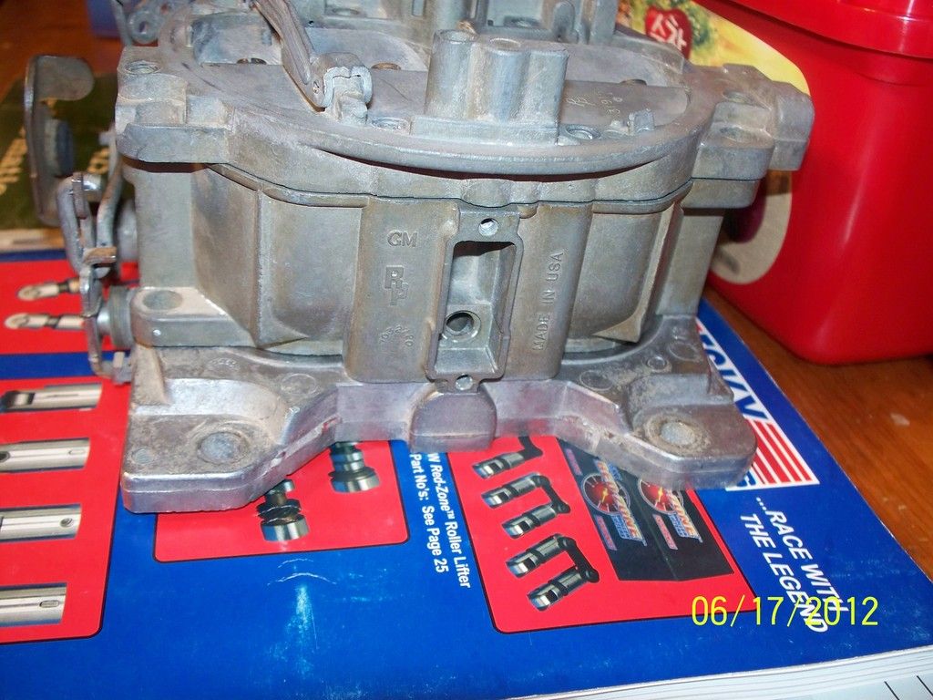
Q-Jets are identified by a number stamped into the Float Bowl casting on the driver’s side of the car just above the secondary throttle linkage. If the carb is a Carter manufactured under license from Rochester, the number will be inside a round metal foil tag on the driver’s side of the carb just above the primary throttle linkage.


Metering Area

WOT fuel mixture is controlled only by the main jet size. Performance at cruise and at idle is then controlled by the rods. We can establish each of these mixtures independently of the other by knowing and understanding the concept of Metering Area.

Jet and rod sizes are always referred to by their diameter in thousands of an inch. But fuel flow doesn’t “see” diameters: The fuel “sees” the total metering area. So we must convert the diameter into a resulting area. We remember that the formula for area is r2. Thus a jet with a diameter of .070” has a metering area of:

Radius = ½ diameter

Radius = .035”

.0352 = .00384”

Thus, the metering area of a #70 jet is 3.84 thousands of a square inch.

But wait! There is a rod inserted into the jet, so we must subtract the area of the rod. Let’s say we have a #40 rod in that #70 jet. The area of the rod is:

Radius = ½ diameter

Radius = .020”

.0202 = .00125”

Thus, the area that a #40 rod “plugs off” is 1.25 thousands of a square inch.

The resulting metering area of the #70/#40 combination is thus 3.84 minus 1.25. The total metering area is 2.59 thousands of a square inch. This is the metering area of this rod/jet combination with the rod fully inserted in the jet. In other words, this is the metering area at cruise speed and at idle.

To see the metering area at WOT, we know that all rods have a .026” diameter power tip (except as noted with the “M” series rods). So we run the same calculation for a .026” diameter rod inserted in the jet.

It is these numbers that we will use in all comparisons when making jet changes. We will use these numbers also to look at the percent differences in jet changes.

So that you won’t need to run around with a calculator, my Carb Listing in Table 1 shows the metering areas for every carb listing at both cruise and at WOT (assuming rods with .026” diameter power tips). The number is the metering area in thousands of an inch for a single jet/rod in the carb. This number is effectively how rich/lean the carb is really jetted, and you can directly compare these numbers to see how the various carbs were set up by the factory. By dividing one area into another area, you can see the percentage difference in the jetting.

Figure 2 is a table showing you what the metering area is for every possible jet/rod combination. Each grouping of jets starts off with the rod power tip diameter of .026” so you can see the WOT metering area of that jet size. It then jumps to the first usable rod size.

Tech Tip #1
Before you go trying to fix all the errors of the previous carb tuner, set your carb up to the stock spec for your carb part number. A carb jetted and set up to its stock specs will usually run pretty good on just about any application, and this gives you a good starting point. From there, you can start doing refinements as outlined in this paper.

The carb number on a Q-Jet is usually stamped into the bowl casting on the driver’s side of the carb in the area above the secondary throttle shaft. The number starts with either “70…” or “170…”. If the carb is a Q-Jet manufactured under license by Carter, it will sometimes have the carb number stamped into a foil circle on the driver’s side of the bowl just above the primary throttle shaft.

The carb listing (Figure 1) is a partial listing of popular Q-Jets that I have compiled over the years. It is not a complete listing of every Q-Jet carb. Most notably, I have very few of the truck carbs listed, yet there are many truck carbs running around on passenger cars. I also have not started compiling all the Cadillac, Olds and Buick applications in this chart, but I do update it at irregular intervals. For the latest version with latest updates, drop me an e-mail on occasion to make sure you have the latest chart.

Tech Tip #2
What has a greater effect on performance: primary or secondary jetting? I constantly see people swapping around secondary rods, trying to get the best performance out of their cars. The secondary rods are very easy to change, and since the secondaries are so BIG, the secondary metering has to be the most important, right?

Wrong.

Most Q-Jets are 750 cfm carbs. This is more airflow than most small block engines can ever handle. Yet, GM used Q-Jets on everything from Overhead Cam 6-cylinder Pontiacs and Buick V-6’s, to 500 cube Caddys. How?

The secondary airvalve on the Q-Jet effectively makes the Q-Jet a variable-cfm carb. The spring windup of the airvalve combined with the bleed-off of the choke pulloff diaphragm allow the secondaries to open only as much as the engine can handle. Thus, if the engine can’t handle all of the cfm, the secondaries simply don’t open all the way.

The primary side, however, is used throughout the rpm range. It is always in use, and provides the metering for the majority of the power produced by the engine. Let’s look at the scenario:

You’re at the stoplight. You bring the rpm up slightly against the torque converter – 1500 rpm. You’re on the primary side of the carb only, and this is what is producing all of your torque right now. The light changes, and you put the pedal to the metal. All of your torque at launch is being produced by the primaries only, as the secondaries don’t see enough airflow to open. The rpm comes up quickly: 2000, 2500, and now the secondaries might be starting to crack. Almost all of the air is still passing through the primaries, and the secondaries are now starting to compliment it just a tad. 3000, 4000 rpm, and the secondaries might be half-way open. The primaries are still providing most of the airflow and metering. 5000, 5500 and you hit redline just as the secondaries hit about ¾ open. Second gear, your rpm drops, partially closing the secondaries back up, and you’re back to sucking the majority of the air through the primaries once again.

So we see, the secondaries provide only a compliment to the primaries. The primaries provide the vast majority of the fuel metering, and primary jetting is absolutely the most critical to proper performance. You cannot compensate for poor primary jetting by re-jetting the secondaries. So we are going to concentrate on jetting the primary side for peak performance, and then we will set up the secondary side to provide a proper compliment to the correct primary jetting.

Tech Tip #3
How can you tell if an off-idle stumble is caused by a lean or a rich condition?
A carb running rich, as well as a carb running lean, can cause an off-idle stumble or hesitation upon acceleration. To narrow it down, tap the roll pin out of the accelerator pump lever by using a small pin punch or a small finish nail. I actually use a small, broken drill bit that’s just the right size. Using a hammer, gently tap the roll pin in towards the choke air horn wall. Don’t jam the pin right up against the wall: Leave just a little bit of a gap so you can get a screwdriver blade in between the wall and the pin to pry it back again. With the pin tapped out, remove the accelerator pump lever. I like to do this with the engine running so I won’t have any trouble starting the engine without the accelerator pump. Now, rev the engine a little with the throttle. Notice if the engine seems quicker and more responsive, or if the hesitation & stumble is worse. If the engine actually feels more responsive with the accelerator pump disconnected, you have a rich condition. If the hesitation is worse than before, you have a lean condition. If there is no change whatsoever, you have a non-functional accelerator pump.

To verify a suspected lean condition after this test, simply hold your cupped hand lightly over the choke air horn area with the engine running at idle, restricting the air flow. If the idle speed and idle quality momentarily increases, you have a verified lean condition. You need to select a jet/rod combination that will give you a little more Cruise Metering Area. Make these changes in less than 10% increments using the Figures provided in this paper.

Tech Tip #4
How can you tell if your power piston spring is too stiff and not allowing the power piston to “seat” at idle?
If your engine does not produce enough manifold vacuum at idle and/or cruise (due to a lumpy cam or other engine parameters), it is possible that the power piston is not being pulled all the way down to its seated position due to the power piston spring being too stiff. The result is that the car will run very rich at idle, and the idle mixture screws will have little effect or response. Idle speed may also “float,” with idle speed starting high and gradually decreasing until the engine stalls due to the engine getting “loaded up.” There will typically be a puff of black smoke out the tailpipes when you “flick” the throttle.

To test for this, pop the top off the carb, remove the power piston/rod assembly, and remove the power piston spring from its bore. Re-install the rod/piston assembly without the spring and put the carb back together. The carb will now run in the full-lean condition all the time, and you can actually test drive it in this condition. You can also test for this condition very quickly (although you cannot actually drive the car) by inserting a long pin punch or a small long screwdriver down through the vent tube: Angle the pin punch slight forward, and you will hit the top of the power piston. You can now depress the power piston and/or verify if it is pulled down into its fully seated position. Be very careful when doing this so you do not jam the punch or screwdriver through your float. If this clears up the idle, improves idle mixture screw response, and eliminates the black smoke when you flick the throttle, you need to install a softer spring. Edelbrock has a complete power piston spring assortment available. You can also get many of the springs from GMPartsDirect using the GM part number shown in the carb listing chart.

Tech Tip #5
How can you tell how stiff the power piston spring needs to be, and how can you tell one spring from another?

If you have a few springs of various kinds laying around, it is not readily apparent which spring is stiffer than another. You can arrange them and order them from softest to stiffest as follows:

Using your carb, or a junk float bowl from another carb, as a testbed, remove the carb air horn (the “top” of the carb) and remove the power piston and its spring. Remove the primary metering rods from the piston. Now, drop a spring into the power piston bore and install the piston. Find a Phillips screwdriver, and place the handle of the screwdriver on top of the power piston with the shank of the screwdriver pointing straight up. Use a screwdriver that is light enough to NOT compress the power piston and its spring, but close. Now, drop flat washers onto the shank of the screwdriver and keep stacking them up until the piston compresses the spring and seats in the bore. Count the number of washers it took to compress the spring and label the spring as a “6-washer spring,” for instance. Do the same with the other springs you want to test. You’ll end up with a comparative rating of springs, like “4-washer,” “6-washer,” or “10-washer” springs. You now know exactly how to arrange them from softest to stiffest.

But which one should you use? You’ll need a junk Q-Jet float bowl for this test, and you’ll need to have your engine in running condition.

Using a stripped down, bare Q-Jet float bowl, you’ll notice that there is a hole in the bottom of the bowl right underneath the power piston bore. This is the vacuum hole that applies manifold vacuum to the power piston. Hook up a long vacuum hose to a manifold vacuum source on your engine. Now, install a power piston spring from your arranged spring selection into the piston bore and install a power piston on top of the spring. Start your engine, and stick the end of the vacuum hose onto the hole in the bottom of the stripped down float bowl. With the engine at idle, the vacuum applied to the bowl should immediately pull the power piston down against the spring pressure and seat the power piston firmly in its bore. If the piston does not fully seat, you need a softer spring from your arranged spring selection. If you have an automatic, put the transmission in “drive.” Make sure the power piston stays seated.

If you really want to do some testing, you can string the vacuum hose into the car, and with an assistant, drive the car around and observe under what conditions the power piston starts to unseat: While you drive, have the assistant stick the vacuum hose onto the bottom of the bowl, and observe what the piston does under various engine loads. Make sure you have a spring that’s stiff enough to make the piston pop up when your engine is under load, yet soft enough to keep the piston fully seated at idle, at cruise and under light acceleration. This makes for some really fun testing, and the results will pay off in a precisely matched power valve spring for some outstanding throttle response.

Of course, if you buy the power piston spring assortment kit from Edelbrock, the springs will be identified and labeled as to their vacuum rating. Select and use a spring with a rating about 1.5” to 2” lower than the idle vacuum of the engine (in drive).

Tech Tip #6
The idle metering circuit on a Q-Jet is not an independent, stand-alone circuit. The idle mixture screws in the throttle plate receive their fuel through the main metering jets. Thus, a change in the main metering circuit (jets and/or rods) will affect the idle circuit. The idle mixture screws cannot meter more fuel than the main jets/rods will allow. Thus, if your Cruise Metering Area jet/rod combination is too lean, you may find that your idle mixture screws are ineffective. If your idle surges, is rough & unstable, and adjusting the screws seems to make no difference (but you can kill the engine by turning them all the way in), chances are good that your cruise metering area is too lean. You can verify this by running your mixture screws out to the point where additional turns have no effect on idle. Then cover the choke area of the carb with your hand. If idle speed & quality increases as you restrict the air flow, your jet/rod combination is too lean.


Procedure
Here is my recommended sequence and procedure for doing a basic Q-Jet set-up:

1. Set the float level.
You’ll be amazed how many people try tuning a Q-Jet without ever checking the float level. An incorrect float level can give you all kinds of symptoms and problems, so get this one set right off the bat. Also, many commercially rebuilt Q-Jets have brass floats. I do not recommend use of a brass float in a Q-Jet. Use the correct “NitroFill” float available from NAPA/Echlin. Part number for most pre-75 Q-Jets is 2-440. Part number for most 75-80 Q-Jets is 2-442.

You have to pull the top of the carb off to set the float level. With the top removed, remove the big phenolic spacer that covers the area around the needle/seat. Hold the float hinge clip firmly seated and push down lightly on the float where it contacts the needle. Measure from the top of the float bowl to the top of the float at the rear edge of the float. Float level should be .375” for a street-driven car using a 1968 – 1974 carb; you can run it at .250” for racing. Early Q-Jets (1968-1972) can be successfully run on the street with the high float level, but you may see some fuel saturation of the air horn gasket with associated gas fumes. Later carbs (1975 and newer) do not run well in street applications with the high float level – run the 1975 + carbs at .420” on the float level. Adjust the float level by removing the float and bending its lever arm. Never raise the float level by forcing the float against the needle/seat to bend it – this will damage the needle.

2. Determine main jet size.
If you have a stock engine, always start with the stock jet size for the carb number you are using and work from there. If you have the typical street modifications like headers, good exhaust system and a free-flowing intake, you can start with a main jet size 2 sizes larger than stock.

Since we want to work on the primary side only, we don’t want the secondaries interfering with the jetting process. Chevy Q-Jets have a secondary lockout lever on the passenger side of the carb right at the secondary throttle shaft. This lever is actuated by the choke linkage, and prevents the secondaries from opening when the engine is cold. I call this the “primary jet tuning lever.” Use a piece of wire or string to engage the lever with the secondaries so that the secondaries cannot be opened.

You now need to find a short flat stretch of road to test drive the car. You need to be able to measure time-to-distance and/or speed-at-distance. I usually find a repeatable stretch of road about 300 feet long. This gets me through 1st gear and into 2nd. Make two or three runs on the car through this stretch and make note of time and speed to distance. Also note the seat-of-your-pants feel of the car (it’s going to feel pretty slow with the secondaries locked out…).

I recommend making jet changes in less than 10% increments. Go to Figure 2 and determine your WOT metering area for your current jet size. This will be the metering area of the jet with the .026” rod. With this number, go to the Jet % Change Chart and find the closest metering area match in the left vertical Metering Area column (Use the “Area” column and not the Jet Size column. The Jet Size column can only be used on carbs that do not employ a metering rod, such as Holley and Weber.). Follow the row across until you get into the “green” zone and find the closest number to 10%, but not greater than 10%. Now go straight up until you get to the new metering area number. This is your target. Take this number and go back to Figure 2 and find the closest jet size that will produce this metering area with a .026” rod. This is the first jet size you want to try, and this will increase your fuel mixture by the percentage indicated in the chart.

Now, to keep your off-idle mixture unaltered, you also need to check your cruise metering area. Go to Figure 2 and find your old main jet & rod combination. Note the resulting metering area for this combination. Now, go to your new main jet size that you’re going to be using and find the rod needed to produce the same cruise metering area you had before. Use this rod with the new jet.

By doing this, you are now changing only 1 parameter at a time: WOT mixture only. Idle, off-idle, and everything else is now unchanged, and you will be able to see the results from the mixture change at WOT only. With the secondaries still locked out, run the car 2 – 3 times down the same stretch and record results. If the numbers get better, you’re going the right way with the main jet size. If the numbers are worse, you need to make changes to the lean side instead of rich. Repeat this operation until you determine the main jet size that produces the best numbers. On many stock cars, you may be surprised to learn that you end up with the stock jet size. You have now optimized main jets.

3. Determine main metering rod size.

NOTE: There are two different “series” of primary metering rods. Q-Jets up through 1974 (the “4MV” series carbs) use the early series rods. 1975 and later Q-Jets (the “M4M” series carbs) use the second series rods. Pre-’75 (up through ’74) Q-Jets use metering rods that are approximately 2.47” long overall (total length from the metering tip to the extreme top of the rod). 1975 and newer Q-Jets use rods that are about 2.40” long. You cannot interchange the two different rod series. The late style rods are also available in the “M” series rods, designed for truck applications. These have fat, .036” diameter power tips on them, and should not be used unless you re-calculate the resultant WOT metering areas and account for this in your tuning. For example: A regular ’76 Vette carb might have a 77/48 jet/rod combination with the correct .026” diameter power tip rods. This gives you a WOT metering area of 4.12 thousands of an inch. If you use a 48M rod in the same carb, you end up with a WOT metering area of only 3.63 thousands. This is the same as if you dropped the main jet size down to a size 73 with the standard-tipped rods. Keep these relationships in mind when playing with rods. Currently, there are no second series .026” power tip primary rods available from any source – all second series rods are “M” series truck rods, including those sold by Edelbrock.

When switching main jets around in Section 2 above, you were also swapping out metering rods to keep the cruise metering area unchanged. You did this to make sure that your off-idle throttle response remained unchanged so that the throttle response off idle did not affect the tuning results from the main jet re-sizing. Now, with your new main jets, your cruise metering area is exactly the same as it was before, but that’s not to say it’s right.

There are several indicators of correct cruise metering area. First, check out Tech Tip #5 regarding the idle circuit. This is a good indication of a lean condition. But here’s another good indicator of correct cruise metering area:

A Q-Jet, when set up with the correct metering rod for cruise & idle, will produce a slight hesitation upon acceleration if the accelerator pump is disconnected. Using a small pin punch or a finish nail, carefully knock out the roll pin securing the accelerator pump arm to the top of the carb. I do this with the engine running so I don’t have any trouble starting the engine without the accelerator pump. With the pump disconnected and with the engine running in neutral, “flick” the throttle just a little. If the engine actually feels more responsive with the pump disconnected, your cruise metering area is too rich, and you need to install a fatter set of rods. If you get a severe stumble, or if the engine dies, you’re on the lean side and need smaller rods. When the rods are correct for the jets in use, you will get a slight hesitation when the pump is disconnected.

Once you have set the rod size up like this, verifying both the idle as shown in Tech Tip #5 and using the disconnected accelerator pump, a road test is in order. If the car is a little “flat” on light acceleration, or if it has a slight “surge” at steady cruise, you need to richen up the metering area slightly. If it is smooth and responsive on light acceleration, and feels smooth at cruise, you have the rod size nailed down.

Again, use the charts to keep all changes limited to 10% at a time. This will prevent you from “over-shooting.” Remember, with the main jet size determined, your rod sizing is affecting idle, off-idle, light acceleration, and cruise. In most cases, when there are problems with stumbles, poor idle, idle speed that starts out high and then degrades, and surging at cruise, the rods are too big and are causing a lean condition. On the other hand, if the rods are too small, causing a rich condition, the throttle will feel “lazy” or “slow” when you rev the engine, and you may get a puff of black smoke with a hesitation when you “flick” the throttle. Correct rods will produce crisp, clean and instant throttle response.

4. Determine secondary rod size.
You are now finally ready to unlock the secondaries. But before you start changing the rods, you want to get the secondary opening rate set up. This is determined by the spring windup.

It is a very common “speed trick” to loosen the secondary windup spring so that the secondaries will open very quickly. This is the single most common cause of a severe stumble or hesitation upon acceleration or transition into the secondaries.

The secondary spring windup is adjusted with a small, slotted-head screw on the passenger side of the carb, right at the top of the carb on the secondary side. The screw head points right out to the side. 90 degrees from this, on the bottom, there is an allen-head lock screw that keeps the slotted screw from turning. If you have trouble seeing it, place a mirror under the area until you spot it. With a small slotted screwdriver holding the adjustment screw, loosen the allen screw about ¼ turn. This will allow you to turn the slotted adjustment screw. Counting the turns, allow the slotted screw to slowly unwind until all spring tension is gone. You can use your mirror to see the spring disengage contact from the pin lever underneath the air horn. If the spring tension was lost after only ½ turn, the windup was too loose. Bring the spring into contact with the lever. Note when it just barely touches. From this point, wind the spring up between ¾ turn and 7/8 turn. This is a good starting point, and will prevent any bogs or hesitations due to premature secondary opening.

Now, you need to adjust the secondary rod hanger height. You’ve read all about the different letter numbers for the secondary hangers, and how a “Y” hanger will make your car faster than an “M” hanger or whatever. Fact is, you can bend and adjust any hanger to any hanger height you want, so it doesn’t make a heck of a lot of difference what hanger you choose to use. Just get it set up right:

With the secondary airvalve held wide open and the secondary rods pulled all the way up, measure the distance from the top of the rear wall of the choke horn to the secondary rod hanger hole in the hanger. This distance should be 41/64”. Bend the hanger to adjust – you have to adjust each of the two sides independently. You now have a “performance” rod hanger.

With this set, you can now play with secondary metering rods. A common speed trick mistake is to always install thinner (richer) secondary rods. Some engines and carbs will produce a secondary “lag” if the rods are too thin. On about half of the engines I work on, I obtain better performance by installing fatter “non-performance” rods. Again, a quick road test is the only way to set this up, so go back to your 300-foot stretch and make a few runs with rods both richer and leaner. Once you have found the rods producing the smoothest secondary transition and the best numbers, you can start unwinding the secondary airvalve spring. Relax the spring tension in 1/8 turn increments until the car stumbles on acceleration, then tighten up 1/8 turn again. You have now determined the quickest secondary opening rate that your engine can handle, and your secondary mixture is set.

Note that secondary metering rods come in three different tapers: long tip, short tip, and medium tip (see Figure 3). Most of the available after-market metering rods have the long tips, and these will produce a full-rich mixture upon the slightest opening of the secondaries. Many street engines will produce better performance by using the short tipped rods. A short tipped rod does not allow a full-rich mixture until the secondaries are opened quite a ways, keeping the mixture a little lean initially. This can produce smoother and crisper performance in many applications. Next time you see a junk Q-Jet laying around, make sure you yank the rods and jets out of it: many old truck carbs have some really good short-tipped secondary rods in them. Figure 3 lists all the secondary rod letter codes, part numbers, and measurements.


Parts
If you don’t have a stash of used Q-Jets in your basement to rob jets and rods out of, you can get parts from Edelbrock. Your local parts store should be able to order them for you. Following is a partial listing of Edelbrock Q-Jet parts and part numbers:

Primary Metering Rods (pairs) for 1974 & earlier:
.035” #1936 .039” #1939 .043” #1944
.037” #1937 .041” #1942 .045” #1946

Primary Metering Rods (pairs) for 1975 & later (NOTE: These are “M”-series rods with .036” power tips!):
.048” #1941 .052” #1945
.050” #1943 .054” #1947

Secondary Metering Rods (pairs) for all years:
CC #1950 CK #1952 CL #1954
CE #1951 AY #1953

Primary Metering Jets (pairs) for all years:
.068” #1968 .072” #1972 .076” #1976
.069” #1969 .073” #1973 .077” #1977
.070” #1970 .074” #1974
.071” #1971 .075” #1975


You can also order a very few original GM parts from GMPartsDirect on the Internet. The following is a complete listing of the GM part numbers for all available Q-Jet jetting components. These parts are being discontinued quickly, so some parts may no longer be available. Any parts available from GMPartsDirect are also available from any GM dealer (if they want to order them for you). You can also get most of these parts from Carbs Unlimited, although they only offer the early primary metering rods:
Primary Metering Rods, ’74 & earlier:
All rods have been discontinued
Primary Metering Rods, ’75 and later:
There are no post-’75 passenger car (.026” power tip) available from GM at this time.
Secondary Rods:
Code P/N Dia of Tip Tip Length (Short, Medium, Long)
AX 7033549 0.0400 S
BG 7034822 0.0400 M
AH 7033812 0.0530 M
AN 7034320 0.0700 S

Primary Metering Jets:
7031969
7031970
7031971
7031973
7031974
7031975
7031978

The last good aftermarket source for Q-Jet parts is from Carbs Unlimited. They carry a full line of jets and the rods for the early applications. They also carry parts such as choke pulloffs, inlet fittings, springs, and linkages. Go to their website to see a full line of parts.

Questions, Comments & Technical Assistance
If you have questions or comments regarding this article, or if you notice any errors that need to be corrected (which is quite possible since I’m writing this from memory…), please feel free to drop me an e-mail. Also, if you need any technical assistance or advice regarding this process, or other maintenance issues, feel free to contact me:

V8FastCars@msn.com


Figure 1: Carb part number listing & stock jetting
(Green highlights show parts that are still available from GM)

Carb # Application Main Jet Main Rod Spring Sec. Rod Jet Area Jet Area
As of 9-26-07: (1 Jet, .001") (1 Jet, .001")
Green highlight = GM parts still available Cruise WOT

7025200 Chev 65 396 AT EARLY 71 44 7029922 7031208 2.4387 3.4283
7025201 Chev 65 396 MT EARLY 71 41 7029922 7031208 2.6389 3.4283
7025220 Chev 65 396 AT LATE 71 44 7029922 7031208 2.4387 3.4283
7025221 Chev 65 396 MT LATE 71 44 7029922 7031208 2.4387 3.4283
7026200 Chev 66 396 AT 71 44 7029922 AX 2.4387 3.4283
7026201 Chev 66 396 MT 71 41 7029922 AX 2.6389 3.4283
7026202 Chev 66 327 AT EARLY 71 45 7029922 AK 2.3688 3.4283
7026203 Chev 66 327 MT 71 43 7029922 AK 2.5070 3.4283
7026204 Chev 66 427 AT 71 46 7029922 AX 2.2973 3.4283
7026205 Chev 66 427 MT 71 41 7029922 AX 2.6389 3.4283
7026210 Chev 66 327 AT LATE 71 45 7029922 AK 2.3688 3.4283
7027200 Chev 67 396/427 AT W/O A.I.R. 71 44 7029922 AX 2.4387 3.4283
7027201 Chev 67 396/427 MT W/O A.I.R. 71 41 7029922 AX 2.6389 3.4283
7027210 Chev 67 396/427 AT 71 44 7029922 AX 2.4387 3.4283
7027211 Chev 67 396/427 MT 71 41 7029922 AX 2.6389 3.4283
7027216 CHEV 67 396/427 W/O A.I.R. 71 44 7029922 AX 2.4387 3.4283
7027218 CHEV 67 327/350 W/O A.I.R. 71 45 7029922 AX 2.3688 3.4283
7027262 Pont 67 400 AT & MT GTO 70 41 7002071 BF 2.5282 3.3175
7027263 Pont 67 400 MT w/o A.I.R. 70 39 7002071 BF 2.6539 3.3175
7028207 Chev 68 327/350 MT VETTE 71 46 7036019 AN 2.2973 3.4283
7028208 Chev 68 327/350 AT VETTE 71 46 7036019 AN 2.2973 3.4283
7028209 Chev 68 427 HIGH PERF MT VETTE 71 45 7036019 AX 2.3688 3.4283
7028210 CHEV 68 396 & 427 STD AUTO 71 49 7036019 AX 2.0735 3.4283
7028211 CHEV 68 396 & 427 STD MANUAL 71 45 7036019 AX 2.3688 3.4283
7028212 Chev 68 327/350 AT 71 46 7036019 AN 2.2973 3.4283
7028213 Chev 68 327/350 FULL-SIZE & TRUCK MT 71 46 7036019 AN 2.2973 3.4283
7028216 Chev 68 427 HIGH PERF AT VETTE 71 47 7036019 AX 2.2242 3.4283
7028217 Chev 68 396 HI PERF MT VETTE & TRUCK 71 45 7036019 AX 2.3688 3.4283
7028218 Chev 68 396 HIGH PERF AT VETTE 71 47 7036019 AX 2.2242 3.4283
7028219 Chev 68 HIGH PERF MT VETTE 66 36 7036019 BG 2.4033 2.8903
7028229 Chev 68 HIGH PERF MT CHEVY II 66 36 7036019 BG 2.4033 2.8903
7028240 Buik 68 430 AT 70 44 7011957 AY 2.3279 3.3175
7028262 Pont 68 400 STD AT 73 43 7037305 BE 2.7332 3.6545
7028263 Pont 68 400 MT GTO 72 40 7037305 BE 2.8149 3.5406
7028267 Pont 68 400 H.O. MT GTO 72 41 7037305 BE 2.7512 3.5406
7028268 Pont 68 400 & 400 H.O. AT GTO 73 42 7037305 BE 2.7999 3.6545
7028268 Pont 68 GTO Best Tuned Condition 71 42 7037305 DA 2.5737 3.4283
7028270 Pont 68 400 RAM AIR AT after Jan 68 72 41 7037305 BE 2.7512 3.5406
7028270 Pont 69 400 AT RAM AIR III 72 41 7037305 BE 2.7512 3.5406
7028273 Pont 68 400 RAM AIR MT after Jan 68 72 42 7037305 BE 2.6861 3.5406
7028273 Pont 69 400 MT RAM AIR III 72 42 7037305 BE 2.6861 3.5406
7028274 Pont 68 400 AT EARLY RAM AIR 73 41 7037305 BE 2.8651 3.6545
7028275 Pont 68 400 MT EARLY RAM AIR 72 40 7037305 BE 2.8149 3.5406
7029200 CHEV 69 CAMARO, VETTE 396/427 AUTO 71 49 7036019 BC 2.0735 3.4283
7029201 CHEV 69 CAMARO, VETTE 396/427 MAN 71 45 7036019 BC 2.3688 3.4283
7029202 Chev 69 350 300HP AT VETTE 67 42 7036019 AN 2.1402 2.9947
7029203 Chev 69 350 300HP MT VETTE 67 38 7036019 AN 2.3915 2.9947
7029204 CHEV 69 CAMARO, VETTE 396/427 AUTO 71 47 7036019 AX 2.2242 3.4283
7029207 Chev 69 350 325HP VETTE 66 36 7036019 BG 2.4033 2.8903
7029214 CHEV 69 396 TRUCK 71 45 7037851 BC 2.3688 3.4283
7029215 Chev 69 396/427 MT 71 45 7036019 AX 2.3688 3.4283
7029223 CHEV 69 350 TRUCK M/T 67 38 7037851 AN 2.3915 2.9947
7029224 CHEV 69 350 TRUCK A/T 67 38 7037851 AN 2.3915 2.9947
7029230 CAD 69 472 STD W/O A/C 70 44 7037298 BH 2.3279 3.3175
7029231 CAD 69 472 STD A/C 70 44 7037298 BH 2.3279 3.3175
7029232 CAD 69 472 EL DORADO W/O A/C 70 42 7037298 BH 2.4630 3.3175
7029233 CAD 69 472 EL DORADO A/C 70 42 7037298 BH 2.4630 3.3175
7029263 Pont 69 400 MT GTO 71 44 7037305 BE 2.4387 3.4283
7029268 Pont 69 400 AT GTO 71 44 7037305 BE 2.4387 3.4283
7029270 Pont 69 400 AT RAM AIR IV 69 38 7037305 BP 2.6052 3.2084
7029273 Pont 69 400 MT RAM AIR IV 69 37 7037305 BP 2.6641 3.2084
7037200 Chev 67 396/427 AT A.I.R. 71 46 7029922 AX 2.2973 3.4283
7037201 Chev 67 396/427 MT A.I.R. 71 41 7029922 AX 2.6389 3.4283
7037210 CHEV 67 396/427 aT A.I.R. LATE 71 46 7029922 AX 2.2973 3.4283
7037211 CHEV 67 396/427 MT A.I.R. LATE 71 41 7029922 AX 2.6389 3.4283
7037213 Chev 67 327 & 350 2nd type MT w/o A.I.R. 71 43 7029922 AN 2.5070 3.4283
7037216 CHEV 67 396/427 A.I.R. 71 46 7029922 AX 2.2973 3.4283
7037218 CHEV 67 327/350 A.I.R. 71 45 7029922 AX 2.3688 3.4283
7037262 Pont 67 400 AT w/A.I.R. GTO 70 40 7002071 BF 2.5918 3.3175
7037263 Pont 67 400 MT w/A.I.R. GTO 70 38 7002071 BF 2.7143 3.3175
7037271 Pont 67 400 RAM AIR after 6 Feb 67 70 38 7002071 BF 2.7143 3.3175
7040200 CHEV 70 CHVL, VETTE BB AUTO 78 49 7036019 BG 2.8926 4.2474
7040201 CHEV 70 CHVL, VETTE BB 4-SPD 78 48 7036019 BG 2.9688 4.2474
7040202 CHEV 70 CHEVELLE, CAMARO 350 AUTO 76 44 7036019 BA 3.0159 4.0055
7040203 CHEV 70 CHEVELLE, CAMARO 350 4-SPD 76 44 7036019 BA 3.0159 4.0055
7040204 CHEV 70 CHVL, VETTE BB AUTO 78 49 7036019 AX 2.8926 4.2474
7040205 CHEV 70 CHVL, VETTE BB 4-SPD 78 49 7036019 AX 2.8926 4.2474
7040206 CHEV 70 TRUCK 396 FED 75 42 7036019 BG 3.0324 3.8869
7040207 CHEV 70 350 FEDERAL VETTE M/T 76 44 7036019 BA 3.0159 4.0055
7040208 CHEV 70 TRUCK 350 FED 75 39 7036019 BA 3.2233 3.8869
7040213 CHEV 70 VETTE 350 4-SPD 76 44 7036019 BA 3.0159 4.0055
7040221 CHEV 70 CHVL, VETTE BB 4-SPD 78 48 7036019 BG 2.9688 4.2474
7040253 OLDS 70 CUTLASS & 442 455 69 7040699 7037734 AU ########## 3.2084
7040263 Pont 70 400 MT FEDERAL GTO 71 44 7037305 CC 2.4387 3.4283
7040264 Pont 70 400 AT FEDERAL GTO 70 41 7037305 BP 2.5282 3.3175
7040267 Pont 70 455 MT FEDERAL GTO 71 42 7037305 CC 2.5737 3.4283
7040268 Pont 70 455 AT FEDERAL GTO 71 42 7037305 CC 2.5737 3.4283
7040270 Pont 70 400 & 455 RAM AIR AT GTO 70 39 7037305 CC 2.6539 3.3175
7040273 Pont 70 400 & 455 RAM AIR MT GTO 70 39 7037305 CC 2.6539 3.3175
7040500 CHEV 70 CHVL, VETTE BB AUTO CALIF 78 49 7036019 BG 2.8926 4.2474
7040501 CHEV 70 CHVL, VETTE BB 4-SPD CALIF 78 48 7036019 BG 2.9688 4.2474
7040502 CHEV 70 CHVL, CAM 350 AUTO CALIF 76 44 7036019 BA 3.0159 4.0055
7040503 CHEV 69 350 300hp CAMARO Best Tuned 74 43 7036019 AK 2.8486 3.7699
7040503 CHEV 70 CHVL, CAM 350 4-SPD CALIF 76 44 7036019 BA 3.0159 4.0055
7040504 CHEV 70 CHVL, VETTE BB AUTO CALIF 78 49 7036019 BG 2.8926 4.2474
7040505 CHEV 70 CHVL, VETTE BB 4-SPD CALIF 78 49 7036019 BG 2.8926 4.2474
7040507 CHEV 70 VETTE 350 4-SPD CALIF 76 44 7036019 BA 3.0159 4.0055
7040509 CHEV 70 TRUCK 396 CALIF 78 49 7036019 BG 2.8926 4.2474
7040511 CHEV 70 TRUCK 350 CALIF 76 44 7036019 BA 3.0159 4.0055
7040513 CHEV 70 VETTE 350 4-SPD CALIF 76 44 7036019 BA 3.0159 4.0055
7040521 CHEV 70 CHVL, VETTE BB 4-SPD CALIF 78 48 7036019 BG 2.9688 4.2474
7040563 Pont 70 400 MT CALIFORNIA GTO 68 36 7037305 BU 2.6138 3.1008
7040564 Pont 70 400 AT CALIFORNIA GTO 68 38 7029922 BU 2.4976 3.1008
7040567 Pont 70 455 MT CALIFORNIA GTO 70 40 7029922 BU 2.5918 3.3175
7040568 Pont 70 455 AT CALIFORNIA GTO 69 37 7029922 BU 2.6641 3.2084
7040570 Pont 70 400 & 455 RAM AIR CALIF. 67 33 7037305 CC 2.6704 2.9947
7040573 Pont 70 400 & 455 RAM AIR MT CALIF. 67 33 7037305 CC 2.6704 2.9947
7041200 CHEV 71 CHEVELLE 402/454 AUTO 77 49 7036019 BG 2.7709 4.1257
7041201 CHEV 71 CHEVELLE 402/454 MAN 77 49 7036019 BG 2.7709 4.1257
7041202 CHEV 71 CHEVELLE 350 AUTO 74 44 7036019 AR 2.7803 3.7699
7041203 CHEV 71 CHEVELLE 350 MAN 74 44 7036019 AR 2.7803 3.7699
7041204 Chev 71 454 AT VETTE 77 49 7036019 BG 2.7709 4.1257
7041205 Chev 71 454 MT VETTE 77 49 7036019 BG 2.7709 4.1257
7041206 CHEV 71 402 SERIES 20 & 30 TRUCK 74 42 7036019 BG 2.9154 3.7699
7041208 CHEV 71 350 SERIES 20 & 30 TRUCK 74 39 7036019 BA 3.1062 3.7699
7041209 CHEV 71 402 SERIES 10 TRUCK 77 49 7036019 BG 2.7709 4.1257
7041211 CHEV 71 350 SERIES 10 TRUCK 74 42 7036019 BA 2.9154 3.7699
7041212 CHEV 71 Vette 350 A/T 74 44 7036019 AR 2.7803 3.7699
7041213 CHEV 71 Vette 350 M/T 74 44 7036019 AR 2.7803 3.7699
7041230 CAD 71 472 & 500 STD 71 47 7036019 CE 2.2242 3.4283
7041231 CAD 71 472 & 500 LIMO 71 47 7036019 CE 2.2242 3.4283
7041232 CAD 71 472 & 500 EL DORADO 67 39 7036019 CF 2.3311 2.9947
7041262 Pont 71 455 AT GTO 71 43 7037305 BU 2.5070 3.4283
7041263 Pont 71 400 MT GTO 75 47 7037305 BU 2.6829 3.8869
7041264 Pont 71 400 AT GTO 71 46 7037305 BP 2.2973 3.4283
7041267 Pont 71 455 H.O. MT GTO 73 38 7037305 BP 3.0513 3.6545
7041268 Pont 71 455 H.O. AT GTO 74 43 7037305 BP 2.8486 3.7699
7041270 Pont 71 455 AT RAM AIR 74 43 7037305 BP 2.8486 3.7699
7041273 Pont 71 455 MT RAM AIR 73 38 7037305 BP 3.0513 3.6545
7041273 Pont 71 455 H.O. Best Tuned Condition 72 38 7037305 BP 2.9374 3.5406
7042202 CHEV 72 350 CHVL & VETTE FED A/T 74 45 7036019 DA 2.7104 3.7699
7042203 CHEV 72 Vette Fed M/T 350 74 45 7036019 DA 2.7104 3.7699
7042206 CHEV 72 402 TRUCK SERIES 20 & 30 A/T 72 43 7036019 DA 2.6193 3.5406
7042207 CHEV 72 402 TRUCK SERIES 20 & 30 M/T 72 43 7036019 DA 2.6193 3.5406
7042208 CHEV 72 350 TRUCK SERIES 10 FED A/T 71 36 7036019 CP 2.9413 3.4283
7042210 CHEV 72 350 TRUCK G-10 FED ALL 74 43 7036019 DA 2.8486 3.7699
7042211 CHEV 72 350 TRUCK SERIES 10 FED M/T 74 43 7036019 DA 2.8486 3.7699
7042215 CHEV 72 CHEVELLE MAN 77 45 7036019 CM 3.0662 4.1257
7042216 CHEV 72 Vette A/T 454 77 49 7036019 CM 2.7709 4.1257
7042217 CHEV 72 Vette M/T 454 77 45 7036019 CM 3.0662 4.1257
7042218 CHEV 72 402 TRUCK SERIES 10 A/T 77 45 7036019 CM 3.0662 4.1257
7042219 CHEV 72 402 TRUCK SERIES 10 M/T 77 45 7036019 CM 3.0662 4.1257
7042220 CHEV 72 CHEVELLE AUTO 77 49 7036019 CM 2.7709 4.1257
7042238 cad 72 LIMO 472 & 500 CI 69 43 7029529 BC 2.2871 3.2084
7042262 Pont 71 455 AT CALIFORNIA 72 43 7037305 CR 2.6193 3.5406
7042263 Pont 72 400 MT GTO 72 45 7037305 CS 2.4811 3.5406
7042264 Pont 72 400 AT CALIFORNIA 74 47 7037305 CR 2.5659 3.7699
7042270 Pont 72 455 H.O. AT 71 45 7037305 CR 2.3688 3.4283
7042272 Pont 72 455 AT GTO 72 43 7029922 CR 2.6193 3.5406
7042273 Pont 72 455 H.O. MT 71 43 7037305 CR 2.5070 3.4283
7042273 Pont 73 455 S.D. MT Early 71 43 7037305 CR 2.5070 3.4283
7042274 Pont 72 400 AT FEDERAL 74 47 7029922 CS 2.5659 3.7699
7042276 Pont 72 455 AT HI ALTITUDE 71 43 7037851 CR 2.5070 3.4283
7042278 Pont 72 400 AT HI ALTITUDE 72 46 7037851 CS 2.4096 3.5406
7042902 CHEV 72 Vette Fed A/T 350 74 45 7036019 DA 2.7104 3.7699
7042903 CHEV 72 Vette Calif. M/T 350 74 45 7036019 DA 2.7104 3.7699
7042910 CHEV 72 350 TRUCK SERIES 10 CA A/T 74 43 7036019 DA 2.8486 3.7699
7042911 CHEV 72 350 TRUCK SERIES 10 CA M/T 74 43 7036019 DA 2.8486 3.7699
7043200 CHEV 73 454 all A/T & Truck 77 50 7036019 DA 2.6931 4.1257
7043201 CHEV 73 454 all M/T & Truck 77 48 7036019 DA 2.8471 4.1257
7043202 CHEV 73 350 all Auto & Truck 73 44 7036019 DA 2.6649 3.6545
7043203 CHEV 73 350 all M/T & Truck 73 44 7036019 DA 2.6649 3.6545
7043207 CHEV 73 454 TRUCK FED C20, 30 & P-30 69 39 7036019 DA 2.5447 3.2084
7043208 CHEV 73 350 TRUCK ALL C, P, K 20 & 30 68 36 7037305 DA 2.6138 3.1008
7043210 CHEV 73 350 TRUCK A/T G SERIES 10 73 42 7036019 DA 2.7999 3.6545
7043211 CHEV 73 350 TRUCK M/T G SERIES 10 73 42 7036019 DA 2.7999 3.6545
7043212 CHEV 73 Vette Hi Perf. Auto 74 44 7036019 DA 2.7803 3.7699
7043213 CHEV 73 Vette Hi Perf. M/T 74 44 7036019 DA 2.7803 3.7699
7043215 CHEV 73 350 G&P SERIES 30 MOTORHOME 72 39 7037305 DA 2.8769 3.5406
7043216 CHEV 73 454 P-30 SUBURBAN FED & CAL 77 48 7036019 DA 2.8471 4.1257
7043250 OLDS 73-74 350 CUTLASS A/T 69 7047907 7040498 AS/CG ########## 3.2084
7043262 Pont 73 455 AT 71 41 7029529 CR 2.6389 3.4283
7043263 Pont 73 400 MT 71 43 7037851 CS 2.5070 3.4283
7043264 Pont 73 400 AT 72 43 7029529 DB 2.6193 3.5406
7043265 Pont 73 455 Firebird M/T 71 44 7029922 CR 2.4387 3.4283
7043266 Pont 73 400 LATE AT 72 45 7029529 DB 2.4811 3.5406
7043270 Pont 73 455 S.D. AT 76 51 7029529 BV 2.4936 4.0055
7043272 Pont 73 455 AT HI ALTITUDE 70 41 7029529 CR 2.5282 3.3175
7043273 Pont 73 455 SD MT 75 49 7029529 BV 2.5321 3.8869
7043274 Pont 73 400 AT HI ALTITUDE 72 45 7037851 DB 2.4811 3.5406
7043507 CHEV 73 454 TRUCK CAL C20, 30 & P-30 70 34 7036019 DA 2.9405 3.3175
7044201 CHEV 74 454 CHVL ALL M/T 75 39 7036019 DH 3.2233 3.8869
7044202 CHEV 74 CHEVELLE 350 AUTO & TRUCK 75 46 7029529 CH 2.7560 3.8869
7044203 CHEV 74 CHEVELLE 350 MAN & TRUCK 75 46 7029529 CH 2.7560 3.8869
7044206 CHEV 74 Vette & Nova Fed A/T 75 46 7029529 CH 2.7560 3.8869
7044207 CHEV 74 Vette & Nova Fed M/T 75 46 7029529 CH 2.7560 3.8869
7044208 CHEV 74 350 Camaro Hi Perf. A/T 75 43 7036019 DA 2.9657 3.8869
7044209 CHEV 74 350 Camaro Hi Perf. M/T 75 43 7036019 DA 2.9657 3.8869
7044210 CHEV 74 Vette 350 Hi Perf. A/T 75 43 7036019 DA 2.9657 3.8869
7044211 CHEV 74 Vette 350 Hi Perf. M/T 75 43 7036019 DA 2.9657 3.8869
7044212 CHEV 74 454 TRUCK C20, 30, P30 MTRHM 69 34 7037298 DH 2.8314 3.2084
7044213 CHEV 74 350 TRUCK CK20 & C30 68 36 7037305 CP 2.6138 3.1008
7044214 CHEV 74 350 TRUCK G30 VAN FED 72 39 7037305 CP 2.8769 3.5406
7044215 CHEV 74 350 TRUCK P30 MOTORHOME FED 72 39 7037305 CP 2.8769 3.5406
7044216 CHEV 74 350 TRUCK P20, 30 FED 68 36 7037305 CP 2.6138 3.1008
7044217 CHEV 74 454 TRUCK C30 EXC MTRHM A/T 69 34 7037298 DH 2.8314 3.2084
7044218 CHEV 74 350 VAN & VANDURA FED A/T 75 46 7029529 CH 2.7560 3.8869
7044219 CHEV 74 350 TRUCK ALL FED M/T 75 43 7036019 CH 2.9657 3.8869
7044221 CHEV 74 454 VETTE ALL M/T 75 39 7036019 DH 3.2233 3.8869
7044223 CHEV 74 454 MONTE, VETTE & TRUCK FED A/T 75 41 7036019 DH 3.0976 3.8869
7044224 CHEV 74 350 SPORTVAN, RALLY FED A/T 75 43 7029529 CH 2.9657 3.8869
7044225 CHEV 74 454 VETTE FED A/T 75 41 7036019 DH 3.0976 3.8869
7044226 CHEV 74 WAGON 400 AUTO 73 44 7029529 DL 2.6649 3.6545
7044227 CHEV 74 454 SUBURBAN A/T FED 74 37 7036019 DH 3.2256 3.7699
7044262 Pont 74 Firebird 455 Fed A/T 71 41 7029529 CR 2.6389 3.4283
7044266 Pont 74 ALL AT 72 45 7029529 DB 2.4811 3.5406
7044268 Pont 74 350 AT 72 43 7029529 DB 2.6193 3.5406
7044269 Pont 74 350 MT 68 35 7037851 DB 2.6696 3.1008
7044274 Pont 74 ALL HI ALTITUDE 72 45 7037851 DB 2.4811 3.5406
7044500 CHEV 74 454 MONTE, VETTE & TRUCK CA A/T 75 41 7036019 DH 3.0976 3.8869
7044502 CHEV 74 CHEVELLE 350 A/T CA & TRUCK 75 46 7037851 CH 2.7560 3.8869
7044503 CHEV 74 CHEVELLE 350 M/T CA & TRUCK 75 46 7037851 CH 2.7560 3.8869
7044505 CHEV 74 454 VETTE CA A/T 75 41 7036019 DH 3.0976 3.8869
7044506 CHEV 74 Vette & Nova Calif. A/T 75 46 7037851 CH 2.7560 3.8869
7044507 CHEV 74 Vette & Nova Calif. M/T 75 46 7037851 CH 2.7560 3.8869
7044513 CHEV 74 350 TRUCK CK20 & C30 CALIF 68 36 7037305 CP 2.6138 3.1008
7044512 CHEV 74 454 TRUCK 20, 30, MTRHM CA 69 34 7037298 DH 2.8314 3.2084
7044514 CHEV 74 350 TRUCK G30 VAN CALIF 72 39 7037305 CP 2.8769 3.5406
7044515 CHEV 74 350 TRUCK P30 MOTORHOME CA 72 39 7037305 CP 2.8769 3.5406
7044516 CHEV 74 350 TRUCK P20, 30 CALIF 68 36 7037305 CP 2.6138 3.1008
7044517 CHEV 74 454 TRUCK P30 EXC MTRHM CA 69 34 7037298 DH 2.8314 3.2084
7044527 CHEV 74 400 C20 SUBURBAN ALL TRANS 72 40 7037851 DL 2.8149 3.5406
7044518 CHEV 74 350 MOTORHOME CALIF A/T 75 42 7037851 CH 3.0324 3.8869
7044519 CHEV 74 350 TRUCK ALL CALIF M/T 75 42 7037851 CH 3.0324 3.8869
7044520 CHEV 74 454 SUBURBAN A/T CALIF 75 42 7037851 DH 3.0324 3.8869
7044526 CHEV 74 400 CHVL CA 73 42 7037851 DL 2.7999 3.6545
7044568 PONT 74 350 AT CALIFORNIA 72 43 7029529 DB 2.6193 3.5406
7045183 OLDS 75 350 CUTLASS A/T A/C FED 67 41 7040498 CV 2.2054 2.9947
7045200 Chev 75 454 AT Chevelle/Monte 76 43 7041477 CJ 3.0843 4.0055
7045202 CHEV 75 CAMARO & BLAZER 350 FED A/T 72 46 17052057 CH 2.4096 3.5406
7045203 CHEV 75 CAMARO & BLAZER 350 FED M/T 72 46 17052057 CH 2.4096 3.5406
7045206 CHEV 75 350 NOVA FED A/T 72 46 17052057 CH 2.4096 3.5406
7045207 CHEV 75 350 NOVA FED M/T 72 46 17052057 CH 2.4096 3.5406
7045210 Chev 75 FEDERAL AT HIGH PERF VETTE 72 44 17052057 CH 2.5510 3.5406
7045211 Chev 75 FEDERAL MT HIGH PERF VETTE 72 44 17052057 CH 2.5510 3.5406
7045212 CHEV 454 C10, 20, 30 P30 MTRHM FED 68 33 7037298 DH 2.7764 3.1008
7045213 CHEV & GMC Truck 75-76 Non-CA, HD 68 32 7029862 CP 2.8274 3.1008
7045214 CHEV 350 TRUCK G20, 30 FED 71 39 7037305 CP 2.7646 3.4283
7045215 CHEV 350 P30 MOTORHOME FED 71 39 7037305 CP 2.7646 3.4283
7045216 CHEV & GMC Truck, 75-76 Reg Chassis 68 32 7029862 CP 2.8274 3.1008
7045217 CHEV 454 P30 REG CHASSIS FED 68 33 7037298 DH 2.7764 3.1008
7045218 CHEV 75 350 G-10 VAN A/T 71 44 7041459 CH 2.4387 3.4283
7045219 CHEV 75 350 G-10 VAN M/T 71 44 7041459 CH 2.4387 3.4283
7045220 CHEV 454 TRUCK C-10 FED 70 38 7041477 CJ 2.7143 3.3175
7045221 CHEV 75 454 CHVL & MONTE CNDA A/T 70 38 7041477 CJ 2.7143 3.3175
7045222 Chev 75 AT ALL VETTE 72 46 17052057 CH 2.4096 3.5406
7045223 Chev 75 FEDERAL MT VETTE 72 46 17052057 CH 2.4096 3.5406
7045224 Chev 75 CHVL, MONTE 400 CA A/T 71 46 7037851 DL 2.2973 3.4283
7045225 CHEV 75-76 400 TRUCK G20, 30 FED 71 36 7037305 DL 2.9413 3.4283
7045228 Chev 75 400 FEDERAL AT Chevelle/Monte 71 47 17052057 DL 2.2242 3.4283
7045229 Chev 75 400 MT Truck K-10, 20 FED 69 36 7029862 DL 2.7214 3.2084
7045294 CHEV 75 350 CHVL & MONTE CNDA A/T 72 46 17052057 CH 2.4096 3.5406
7045502 CHEV 75 CAMARO 350 CA A/T 72 46 17052057 CH 2.4096 3.5406
7045503 CHEV 75 CAMARO 350 CA M/T 72 46 17052057 CH 2.4096 3.5406
7045504 Chev 75 350 AT CALIFORNIA 72 46 7037851 CH 2.4096 3.5406
7045506 CHEV 75 350 NOVA CA A/T 72 46 17052057 CH 2.4096 3.5406
7045507 CHEV 75 350 NOVA CA M/T 72 46 17052057 CH 2.4096 3.5406
7045512 CHEV 454 C10, 20, 30, P30 MTRHM CA 67 30 7036019 CJ 2.8188 2.9947
7045512 CHEV 454 P30 EXC MTRHM CA 67 30 7036019 CJ 2.8188 2.9947
7045583 CHEV & GMC Truck, 75-77 Calif. 73 42 7029862 CP 2.7999 3.6545
7045584 CHEV 350 TRUCK G20, 30 CALIF 72 40 7037305 CP 2.8149 3.5406
7045585 CHEV 350 P30 MOTORHOME CALIF 72 40 7037305 CP 2.8149 3.5406
7045586 CHEV & GMC Truck, 75-77 Reg Chassis CA 73 42 7029862 CP 2.7999 3.6545
7045588 CHEV 75-76 400 TRUCK G20, 30 CALIF 73 38 7037305 DL 3.0513 3.6545
7045589 CHEV 75-76 400 TRUCK K10, 20 CALIF 73 33 7037305 DL 3.3301 3.6545
17054919 CHEV SERV REPL 73 VETTE, NOVA, CAM 74 44 7036019 DA 2.7803 3.7699
17054920 CHEV SERV REPL 74 350 VETTE, CAM, CHVL 75 46 7029529 CH 2.7560 3.8869
17054923 GMC SERV REPL 71 350 ALL 74 39 7036019 BA 3.1062 3.7699
17054927 CHEV 72 350 Srv Repl Vette, Camaro, GMC 74 43 7036019 DA 2.8486 3.7699
17054928 CHEV 73 350 TRUCK ALL TRANS 73 42 7029862 DA 2.7999 3.6545
17054929 CHEV 74 350-400 CHVL, VETTE, MONTE 73 42 7037851 CH 2.7999 3.6545
17055038 CHEV 75 Serv Repl Truck, Vette, Nova 72 46 17052057 CH 2.4096 3.5406
17056200 CHEV 76 454 FULL SIZE A/T 79 46 7041477 DR 3.2398 4.3707
17056202 CHEV 76 350 CAMARO FED A/T 77 48 17052057 CH 2.8471 4.1257
17056203 CHEV 76 350 CAMARO FED M/T 77 48 17052057 CH 2.8471 4.1257
17056206 CHEV 76 Vette & Nova A/T 77 48 17052057 CH 2.8471 4.1257
17056207 CHEV 76 Vette & Nova M/T 77 48 17052057 CH 2.8471 4.1257
17056208 CHEV 76 350 TRUCK C10 A/T FED 77 48 17052057 CH 2.8471 4.1257
17056209 CHEV 76 350 TRUCK C10 M/T FED 77 48 17052057 CH 2.8471 4.1257
17056210 Chev 76 FEDERAL AT VETTE 77 51 17052057 CH 2.6138 4.1257
17056211 Chev 76 FEDERAL MT VETTE 77 51 17052057 CH 2.6138 4.1257
17056218 CHEV 76 350 G10 VAN A/T FED 76 47 17052057 CH 2.8015 4.0055
17056219 CHEV 76 350 G10 VAN M/T FED 76 47 17052057 CH 2.8015 4.0055
17056221 CHEV 76 FED HD TRUCK 454 AUTO 77 45 7041477 DR 3.0662 4.1257
17056226 Chev 76 FEDERAL AT A/C VETTE 77 51 17052057 CH 2.6138 4.1257
17056281 CHEV 76-77 CHVL, CAMARO CANADA 77 48 17052057 CH 2.8471 4.1257
17056282 CHEV 76 NOVA, VETTE CANADA 77 48 17052057 CH 2.8471 4.1257
17056283 CHEV 76 350 TRUCK C10 CANADA NO CAT 77 48 17052057 CH 2.8471 4.1257
17056284 CHEV 76 350 G10 VAN CANADA NO CAT 76 47 17052057 CH 2.8015 4.0055
17056286 CHEV 76 454 A/T CANADA 77 45 7041477 DR 3.0662 4.1257
17056502 CHEV 76 350 CAMARO CA A/T 77 48 17052057 CH 2.8471 4.1257
17056503 CHEV 76 350 CAMARO CA M/T 77 48 7037851 CH 2.8471 4.1257
17056506 CHEV 76 Vette & Nova A/T Calif 77 48 17052057 CH 2.8471 4.1257
17056507 CHEV 76 Vette & Nova M/T Calif 77 48 7037851 CH 2.8471 4.1257
17056508 CHEV 76 350 TRUCK C10 A/T CALIF 77 48 7037851 CH 2.8471 4.1257
17056509 CHEV 76 350 TRUCK C10 M/T CALIF 77 48 7037851 CH 2.8471 4.1257
17056512 CHEV 76 CALIF HD TRUCK 454 AT & MT 72 38 7036019 DR 2.9374 3.5406
17056517 CHEV 76 FED P-30 TRUCK 454 AUTO 72 38 7036019 DR 2.9374 3.5406
17056518 CHEV 76 350 G10 VAN A/T CALIF 76 47 7037851 CH 2.8015 4.0055
17056519 CHEV 76 350 G10 VAN M/T CALIF 76 47 7037851 CH 2.8015 4.0055
17057202 CHEV 77 CHVL, MONTE, VETTE 350 AUTO 77 52 7029529 CH 2.5329 4.1257
17057203 Chev 77 FEDERAL MT NON-A/C VETTE 77 52 7029529 CH 2.5329 4.1257
17057204 CHEV 77 CHVL, VETTE 350 AUTO A/C 77 52 7029529 CH 2.5329 4.1257
17057210 Chev 77 HIGH PERF NON-A/C VETTE 77 53 17052057 CH 2.4504 4.1257
17057211 Chev 77 HIGH PERF A/C & NON-A/C VETTE 77 53 17052057 CH 2.4504 4.1257
17057213 Chev 77 HD Truck 350 C-K-G-10-20-30 Fed 64 40 7036019 DP 1.9604 2.6861
17057215 Chev 77 HD P-30 Motor Home 350 Federal 64 40 7036019 DP 1.9604 2.6861
17057216 Chev 77 HD P-30 Conv Chassis 350 Fed 64 40 7036019 DP 1.9604 2.6861
17057222 Chev 77 G10 VAN FED A/C A/T 77 52 7029529 CH 2.5329 4.1257
17057514 Chev 77 HD G-20-30 Van 350 Calif 73 39 7036019 CP 2.9908 3.6545
17057228 Chev 77 FEDERAL A/C VETTE 77 53 17052057 CH 2.4504 4.1257
17057502 CHEV 77 350 NON A/C AUTO CALIF 72 41 7036019 CH 2.7512 3.5406
17057504 CHEV 77 350 A/C AUTO CALIF 72 41 7036019 CH 2.7512 3.5406
17057582 CHEV 77 350 HI ALT NON A/C 72 41 7036019 CH 2.7512 3.5406
17057584 CHEV 77 MONTE CARLO, HI ALT. A/C 72 41 7036019 CH 2.7512 3.5406
17058202 CHEV 78 VETTE 350 FED NO A/C A/T 77 52 7029529 CH 2.5329 4.1257
17058203 CHEV 78 FED VETTE A/C & NON-A/C 4-SPD 77 52 7029529 CH 2.5329 4.1257
17058204 CHEV 78 VETTE 350 FED A/C A/T 77 52 7029529 CH 2.5329 4.1257
17058210 CHEV 78 FED VETTE NON A/C AUTO 77 53 17052057 CH 2.4504 4.1257
17058211 CHEV 78 FED VETTE H.P. A/C & NON 4-SPD 77 53 17052057 CH 2.4504 4.1257
17058213 CHEV 78 GMC HD Truck & '79 Canada HD 63 40 7036019 CP 1.8606 2.5863
17058228 CHEV 78 FED VETTE H.P. A/C AUTO 77 53 17052057 CH 2.4504 4.1257
17058229 CHEV 78 400-454 HD TRUCK FED A/T 64 39 7036019 DG 2.0224 2.6861
17058250 BUICK, OLDS 403 NON A/C FED 73 55 7044432 CV 1.8096 3.6545
17058253 BUICK, OLDS 403 A/C FED 73 55 7044432 CV 1.8096 3.6545
17058258 BUICK, OLDS 403 A/C HI ALT 70 50 17051705 CV 1.8850 3.3175
17058282 CHEV 78 CANADA Z-94 CAMARO NO AC 77 52 7029529 CH 2.5329 4.1257
17058284 CHEV 78 CANADA Z-94 CAMARO AC 77 52 7029529 CH 2.5329 4.1257
17058502 CHEV 78 VETTE 350 CA NO A/C A/T 71 41 7036019 CH 2.6389 3.4283
17058504 CHEV 78 VETTE 350 CA A/C A/T 71 41 7036019 CH 2.6389 3.4283
17058553 BUICK, OLDS, PONT 403 CALIF 74 52 17051705 CV 2.1771 3.7699
17058582 CHEV 78 VETTE 350 HI ALT. NO A/C A/T 71 41 7036019 CH 2.6389 3.4283
17058584 CHEV 78 VETTE 350 HI ALT. A/C A/T 71 41 7036019 CH 2.6389 3.4283
17059203 CHEV 79 FED VETTE A/C & NON 4-SPD 72 40 7036019 CH 2.8149 3.5406
17059205 CHEV 79 350 TRUCK, NON-A/C, AUTO 72 52 7036019 DP 1.9478 3.5406
17059207 CHEV 79 305 EL CAMINO M/T 72 40 7036019 CH 2.8149 3.5406
17059210 CHEV 79 VETTE L-82 H.P. NON-A/C AUTO 77 53 17052057 CH 2.4504 4.1257
17059211 CHEV 79 VETTE L-82 H.P. A/C & NON 4-SPD 77 53 17052057 CH 2.4504 4.1257
17059216 CHEV 79 305-350 CAMARO A/C 72 40 7036019 CH 2.8149 3.5406
17059217 CHEV 79 305-350 CAMARO NO A/C 72 40 7036019 CH 2.8149 3.5406
17059218 CHEV 79 305 MALIBU 2.29 AXLE NO AC 71 40 7036019 CH 2.7026 3.4283
17059222 CHEV 79 305 MALIBU 2.29 AXLE AC 71 40 7036019 CH 2.7026 3.4283
17059228 CHEV 79 VETTE L-82 H.P. A/C AUTO 77 53 17052057 CH 2.4504 4.1257
17059282 CHEV 79 CANADA Z-94 CAMARO NO A/C 77 51 7029529 CH 2.6138 4.1257
17059284 CHEV 79 CANADA Z-94 CAMARO A/C 77 51 7029529 CH 2.6138 4.1257
17059298 VOLVO PENTA, MARINE, 305 69 40 CJ 2.4826 3.2084
17059504 79 SKYLARK, NOVA, CAMARO VETTE CA 72 40 7037305 CH 2.8149 3.5406
17059582 CHEV 79 305 MALIBU NO A/C 71 41 7036019 CH 2.6389 3.4283
17059582 CHEV 79 VETTE 350 HI ALT. NO A/C 71 41 7036019 CH 2.6389 3.4283
17059584 CHEV 79 305 MALIBU A/C 71 41 7036019 CH 2.6389 3.4283
17059584 CHEV 79 VETTE 350 HI ALT. A/C 71 41 7036019 CH 2.6389 3.4283
17080201 CHEV 80 71 48 7036019 DR 2.1496 3.4283
17080202 CHEV 80 71 42 7036019 CH 2.5737 3.4283
17080204 CHEV 80 73 41 7036019 CH 2.8651 3.6545
17080205 CHEV 80 72 51 7036019 DP 2.0287 3.5406
17080206 CHEV 80 72 51 7036019 DP 2.0287 3.5406
17080207 Chev 80 VETTE M/T 71 42 7036019 CH 2.5737 3.4283
17080212 CHEV 80 72 52 7036019 DH 1.9478 3.5406
17080213 CHEV 80 72 50 7036019 DP 2.1080 3.5406
17080215 CHEV 80 72 50 7036019 DP 2.1080 3.5406
17080224 CHEV 80 72 48 7036019 DR 2.2619 3.5406
17080228 CHEV 80 Vette L82 A/T 72 41 7036019 CH 2.7512 3.5406


Figure 2: Metering Areas of Jet & Rod Combinations

Jet Jet Area Rod Rod Area Total Area


0.060 0.00282743 0.026 0.00053093 0.0022965
0.060 0.00282743 0.030 0.00070686 0.00212058
0.060 0.00282743 0.031 0.00075477 0.00207267
0.060 0.00282743 0.032 0.00080425 0.00202319
0.060 0.00282743 0.033 0.0008553 0.00197213
0.060 0.00282743 0.034 0.00090792 0.00191951
0.060 0.00282743 0.035 0.00096211 0.00186532
0.060 0.00282743 0.036 0.00101788 0.00180956
0.060 0.00282743 0.037 0.00107521 0.00175222
0.060 0.00282743 0.038 0.00113411 0.00169332
0.060 0.00282743 0.039 0.00119459 0.00163284
0.060 0.00282743 0.040 0.00125664 0.0015708
0.060 0.00282743 0.041 0.00132025 0.00150718
0.060 0.00282743 0.042 0.00138544 0.00144199
0.060 0.00282743 0.043 0.0014522 0.00137523
0.060 0.00282743 0.044 0.00152053 0.0013069
0.060 0.00282743 0.045 0.00159043 0.001237
0.060 0.00282743 0.046 0.0016619 0.00116553
0.060 0.00282743 0.047 0.00173494 0.00109249
0.060 0.00282743 0.048 0.00180956 0.00101788
0.060 0.00282743 0.049 0.00188574 0.00094169
0.060 0.00282743 0.050 0.0019635 0.00086394

0.061 0.00292247 0.026 0.00053093 0.00239154
0.061 0.00292247 0.030 0.00070686 0.00221561
0.061 0.00292247 0.031 0.00075477 0.0021677
0.061 0.00292247 0.032 0.00080425 0.00211822
0.061 0.00292247 0.033 0.0008553 0.00206717
0.061 0.00292247 0.034 0.00090792 0.00201455
0.061 0.00292247 0.035 0.00096211 0.00196035
0.061 0.00292247 0.036 0.00101788 0.00190459
0.061 0.00292247 0.037 0.00107521 0.00184726
0.061 0.00292247 0.038 0.00113411 0.00178835
0.061 0.00292247 0.039 0.00119459 0.00172788
0.061 0.00292247 0.040 0.00125664 0.00166583
0.061 0.00292247 0.041 0.00132025 0.00160221
0.061 0.00292247 0.042 0.00138544 0.00153702
0.061 0.00292247 0.043 0.0014522 0.00147027
0.061 0.00292247 0.044 0.00152053 0.00140194
0.061 0.00292247 0.045 0.00159043 0.00133204
0.061 0.00292247 0.046 0.0016619 0.00126056
0.061 0.00292247 0.047 0.00173494 0.00118752
0.061 0.00292247 0.048 0.00180956 0.00111291
0.061 0.00292247 0.049 0.00188574 0.00103673
0.061 0.00292247 0.050 0.0019635 0.00095897
0
0.062 0.00301907 0.026 0.00053093 0.00248814
0.062 0.00301907 0.030 0.00070686 0.00231221
0.062 0.00301907 0.031 0.00075477 0.0022643
0.062 0.00301907 0.032 0.00080425 0.00221482
0.062 0.00301907 0.033 0.0008553 0.00216377
0.062 0.00301907 0.034 0.00090792 0.00211115
0.062 0.00301907 0.035 0.00096211 0.00205696
0.062 0.00301907 0.036 0.00101788 0.00200119
0.062 0.00301907 0.037 0.00107521 0.00194386
0.062 0.00301907 0.038 0.00113411 0.00188496
0.062 0.00301907 0.039 0.00119459 0.00182448
0.062 0.00301907 0.040 0.00125664 0.00176243
0.062 0.00301907 0.041 0.00132025 0.00169882
0.062 0.00301907 0.042 0.00138544 0.00163363
0.062 0.00301907 0.043 0.0014522 0.00156687
0.062 0.00301907 0.044 0.00152053 0.00149854
0.062 0.00301907 0.045 0.00159043 0.00142864
0.062 0.00301907 0.046 0.0016619 0.00135717
0.062 0.00301907 0.047 0.00173494 0.00128413
0.062 0.00301907 0.048 0.00180956 0.00120951
0.062 0.00301907 0.049 0.00188574 0.00113333
0.062 0.00301907 0.050 0.0019635 0.00105558

0.063 0.00311725 0.026 0.00053093 0.00258632
0.063 0.00311725 0.030 0.00070686 0.00241039
0.063 0.00311725 0.031 0.00075477 0.00236248
0.063 0.00311725 0.032 0.00080425 0.002313
0.063 0.00311725 0.033 0.0008553 0.00226195
0.063 0.00311725 0.034 0.00090792 0.00220933
0.063 0.00311725 0.035 0.00096211 0.00215513
0.063 0.00311725 0.036 0.00101788 0.00209937
0.063 0.00311725 0.037 0.00107521 0.00204204
0.063 0.00311725 0.038 0.00113411 0.00198313
0.063 0.00311725 0.039 0.00119459 0.00192265
0.063 0.00311725 0.040 0.00125664 0.00186061
0.063 0.00311725 0.041 0.00132025 0.00179699
0.063 0.00311725 0.042 0.00138544 0.0017318
0.063 0.00311725 0.043 0.0014522 0.00166504
0.063 0.00311725 0.044 0.00152053 0.00159671
0.063 0.00311725 0.045 0.00159043 0.00152681
0.063 0.00311725 0.046 0.0016619 0.00145534
0.063 0.00311725 0.047 0.00173494 0.0013823
0.063 0.00311725 0.048 0.00180956 0.00130769
0.063 0.00311725 0.049 0.00188574 0.0012315
0.063 0.00311725 0.050 0.0019635 0.00115375

0.064 0.00321699 0.026 0.00053093 0.00268606
0.064 0.00321699 0.030 0.00070686 0.00251013
0.064 0.00321699 0.031 0.00075477 0.00246222
0.064 0.00321699 0.032 0.00080425 0.00241274
0.064 0.00321699 0.033 0.0008553 0.00236169
0.064 0.00321699 0.034 0.00090792 0.00230907
0.064 0.00321699 0.035 0.00096211 0.00225488
0.064 0.00321699 0.036 0.00101788 0.00219911
0.064 0.00321699 0.037 0.00107521 0.00214178
0.064 0.00321699 0.038 0.00113411 0.00208288
0.064 0.00321699 0.039 0.00119459 0.0020224
0.064 0.00321699 0.040 0.00125664 0.00196035
0.064 0.00321699 0.041 0.00132025 0.00189674
0.064 0.00321699 0.042 0.00138544 0.00183155
0.064 0.00321699 0.043 0.0014522 0.00176479
0.064 0.00321699 0.044 0.00152053 0.00169646
0.064 0.00321699 0.045 0.00159043 0.00162656
0.064 0.00321699 0.046 0.0016619 0.00155509
0.064 0.00321699 0.047 0.00173494 0.00148205
0.064 0.00321699 0.048 0.00180956 0.00140743
0.064 0.00321699 0.049 0.00188574 0.00133125
0.064 0.00321699 0.050 0.0019635 0.0012535

0.065 0.00331831 0.026 0.00053093 0.00278738
0.065 0.00331831 0.030 0.00070686 0.00261145
0.065 0.00331831 0.031 0.00075477 0.00256354
0.065 0.00331831 0.032 0.00080425 0.00251406
0.065 0.00331831 0.033 0.0008553 0.00246301
0.065 0.00331831 0.034 0.00090792 0.00241039
0.065 0.00331831 0.035 0.00096211 0.00235619
0.065 0.00331831 0.036 0.00101788 0.00230043
0.065 0.00331831 0.037 0.00107521 0.0022431
0.065 0.00331831 0.038 0.00113411 0.00218419
0.065 0.00331831 0.039 0.00119459 0.00212372
0.065 0.00331831 0.040 0.00125664 0.00206167
0.065 0.00331831 0.041 0.00132025 0.00199805
0.065 0.00331831 0.042 0.00138544 0.00193286
0.065 0.00331831 0.043 0.0014522 0.00186611
0.065 0.00331831 0.044 0.00152053 0.00179778
0.065 0.00331831 0.045 0.00159043 0.00172788
0.065 0.00331831 0.046 0.0016619 0.0016564
0.065 0.00331831 0.047 0.00173494 0.00158336
0.065 0.00331831 0.048 0.00180956 0.00150875
0.065 0.00331831 0.049 0.00188574 0.00143257
0.065 0.00331831 0.050 0.0019635 0.00135481

0.066 0.00342119 0.026 0.00053093 0.00289027
0.066 0.00342119 0.030 0.00070686 0.00271434
0.066 0.00342119 0.031 0.00075477 0.00266643
0.066 0.00342119 0.032 0.00080425 0.00261695
0.066 0.00342119 0.033 0.0008553 0.0025659
0.066 0.00342119 0.034 0.00090792 0.00251327
0.066 0.00342119 0.035 0.00096211 0.00245908
0.066 0.00342119 0.036 0.00101788 0.00240332
0.066 0.00342119 0.037 0.00107521 0.00234598
0.066 0.00342119 0.038 0.00113411 0.00228708
0.066 0.00342119 0.039 0.00119459 0.0022266
0.066 0.00342119 0.040 0.00125664 0.00216456
0.066 0.00342119 0.041 0.00132025 0.00210094
0.066 0.00342119 0.042 0.00138544 0.00203575
0.066 0.00342119 0.043 0.0014522 0.00196899
0.066 0.00342119 0.044 0.00152053 0.00190066
0.066 0.00342119 0.045 0.00159043 0.00183076
0.066 0.00342119 0.046 0.0016619 0.00175929
0.066 0.00342119 0.047 0.00173494 0.00168625
0.066 0.00342119 0.048 0.00180956 0.00161164
0.066 0.00342119 0.049 0.00188574 0.00153545
0.066 0.00342119 0.050 0.0019635 0.0014577

0.067 0.00352565 0.026 0.00053093 0.00299472
0.067 0.00352565 0.030 0.00070686 0.00281879
0.067 0.00352565 0.031 0.00075477 0.00277088
0.067 0.00352565 0.032 0.00080425 0.0027214
0.067 0.00352565 0.033 0.0008553 0.00267035
0.067 0.00352565 0.034 0.00090792 0.00261773
0.067 0.00352565 0.035 0.00096211 0.00256354
0.067 0.00352565 0.036 0.00101788 0.00250778
0.067 0.00352565 0.037 0.00107521 0.00245044
0.067 0.00352565 0.038 0.00113411 0.00239154
0.067 0.00352565 0.039 0.00119459 0.00233106
0.067 0.00352565 0.040 0.00125664 0.00226902
0.067 0.00352565 0.041 0.00132025 0.0022054
0.067 0.00352565 0.042 0.00138544 0.00214021
0.067 0.00352565 0.043 0.0014522 0.00207345
0.067 0.00352565 0.044 0.00152053 0.00200512
0.067 0.00352565 0.045 0.00159043 0.00193522
0.067 0.00352565 0.046 0.0016619 0.00186375
0.067 0.00352565 0.047 0.00173494 0.00179071
0.067 0.00352565 0.048 0.00180956 0.00171609
0.067 0.00352565 0.049 0.00188574 0.00163991
0.067 0.00352565 0.050 0.0019635 0.00156216

0.068 0.00363168 0.026 0.00053093 0.00310075
0.068 0.00363168 0.030 0.00070686 0.00292482
0.068 0.00363168 0.031 0.00075477 0.00287691
0.068 0.00363168 0.032 0.00080425 0.00282743
0.068 0.00363168 0.033 0.0008553 0.00277638
0.068 0.00363168 0.034 0.00090792 0.00272376
0.068 0.00363168 0.035 0.00096211 0.00266957
0.068 0.00363168 0.036 0.00101788 0.00261381
0.068 0.00363168 0.037 0.00107521 0.00255647
0.068 0.00363168 0.038 0.00113411 0.00249757
0.068 0.00363168 0.039 0.00119459 0.00243709
0.068 0.00363168 0.040 0.00125664 0.00237504
0.068 0.00363168 0.041 0.00132025 0.00231143
0.068 0.00363168 0.042 0.00138544 0.00224624
0.068 0.00363168 0.043 0.0014522 0.00217948
0.068 0.00363168 0.044 0.00152053 0.00211115
0.068 0.00363168 0.045 0.00159043 0.00204125
0.068 0.00363168 0.046 0.0016619 0.00196978
0.068 0.00363168 0.047 0.00173494 0.00189674
0.068 0.00363168 0.048 0.00180956 0.00182212
0.068 0.00363168 0.049 0.00188574 0.00174594
0.068 0.00363168 0.050 0.0019635 0.00166819

0.069 0.00373928 0.026 0.00053093 0.00320835
0.069 0.00373928 0.030 0.00070686 0.00303242
0.069 0.00373928 0.031 0.00075477 0.00298451
0.069 0.00373928 0.032 0.00080425 0.00293503
0.069 0.00373928 0.033 0.0008553 0.00288398
0.069 0.00373928 0.034 0.00090792 0.00283136
0.069 0.00373928 0.035 0.00096211 0.00277717
0.069 0.00373928 0.036 0.00101788 0.0027214
0.069 0.00373928 0.037 0.00107521 0.00266407
0.069 0.00373928 0.038 0.00113411 0.00260517
0.069 0.00373928 0.039 0.00119459 0.00254469
0.069 0.00373928 0.040 0.00125664 0.00248264
0.069 0.00373928 0.041 0.00132025 0.00241903
0.069 0.00373928 0.042 0.00138544 0.00235384
0.069 0.00373928 0.043 0.0014522 0.00228708
0.069 0.00373928 0.044 0.00152053 0.00221875
0.069 0.00373928 0.045 0.00159043 0.00214885
0.069 0.00373928 0.046 0.0016619 0.00207738
0.069 0.00373928 0.047 0.00173494 0.00200434
0.069 0.00373928 0.048 0.00180956 0.00192972
0.069 0.00373928 0.049 0.00188574 0.00185354
0.069 0.00373928 0.050 0.0019635 0.00177579

0.070 0.00384845 0.026 0.00053093 0.00331752
0.070 0.00384845 0.030 0.00070686 0.00314159
0.070 0.00384845 0.031 0.00075477 0.00309368
0.070 0.00384845 0.032 0.00080425 0.0030442
0.070 0.00384845 0.033 0.0008553 0.00299315
0.070 0.00384845 0.034 0.00090792 0.00294053
0.070 0.00384845 0.035 0.00096211 0.00288634
0.070 0.00384845 0.036 0.00101788 0.00283057
0.070 0.00384845 0.037 0.00107521 0.00277324
0.070 0.00384845 0.038 0.00113411 0.00271434
0.070 0.00384845 0.039 0.00119459 0.00265386
0.070 0.00384845 0.040 0.00125664 0.00259181
0.070 0.00384845 0.041 0.00132025 0.0025282
0.070 0.00384845 0.042 0.00138544 0.00246301
0.070 0.00384845 0.043 0.0014522 0.00239625
0.070 0.00384845 0.044 0.00152053 0.00232792
0.070 0.00384845 0.045 0.00159043 0.00225802
0.070 0.00384845 0.046 0.0016619 0.00218655
0.070 0.00384845 0.047 0.00173494 0.00211351
0.070 0.00384845 0.048 0.00180956 0.00203889
0.070 0.00384845 0.049 0.00188574 0.00196271
0.070 0.00384845 0.050 0.0019635 0.00188496

0.071 0.00395919 0.026 0.00053093 0.00342826
0.071 0.00395919 0.030 0.00070686 0.00325233
0.071 0.00395919 0.031 0.00075477 0.00320442
0.071 0.00395919 0.032 0.00080425 0.00315494
0.071 0.00395919 0.033 0.0008553 0.00310389
0.071 0.00395919 0.034 0.00090792 0.00305127
0.071 0.00395919 0.035 0.00096211 0.00299708
0.071 0.00395919 0.036 0.00101788 0.00294132
0.071 0.00395919 0.037 0.00107521 0.00288398
0.071 0.00395919 0.038 0.00113411 0.00282508
0.071 0.00395919 0.039 0.00119459 0.0027646
0.071 0.00395919 0.040 0.00125664 0.00270256
0.071 0.00395919 0.041 0.00132025 0.00263894
0.071 0.00395919 0.042 0.00138544 0.00257375
0.071 0.00395919 0.043 0.0014522 0.00250699
0.071 0.00395919 0.044 0.00152053 0.00243866
0.071 0.00395919 0.045 0.00159043 0.00236876
0.071 0.00395919 0.046 0.0016619 0.00229729
0.071 0.00395919 0.047 0.00173494 0.00222425
0.071 0.00395919 0.048 0.00180956 0.00214963
0.071 0.00395919 0.049 0.00188574 0.00207345
0.071 0.00395919 0.050 0.0019635 0.0019957

0.072 0.0040715 0.026 0.00053093 0.00354057
0.072 0.0040715 0.030 0.00070686 0.00336465
0.072 0.0040715 0.031 0.00075477 0.00331674
0.072 0.0040715 0.032 0.00080425 0.00326726
0.072 0.0040715 0.033 0.0008553 0.00321621
0.072 0.0040715 0.034 0.00090792 0.00316358
0.072 0.0040715 0.035 0.00096211 0.00310939
0.072 0.0040715 0.036 0.00101788 0.00305363
0.072 0.0040715 0.037 0.00107521 0.00299629
0.072 0.0040715 0.038 0.00113411 0.00293739
0.072 0.0040715 0.039 0.00119459 0.00287691
0.072 0.0040715 0.040 0.00125664 0.00281487
0.072 0.0040715 0.041 0.00132025 0.00275125
0.072 0.0040715 0.042 0.00138544 0.00268606
0.072 0.0040715 0.043 0.0014522 0.0026193
0.072 0.0040715 0.044 0.00152053 0.00255097
0.072 0.0040715 0.045 0.00159043 0.00248107
0.072 0.0040715 0.046 0.0016619 0.0024096
0.072 0.0040715 0.047 0.00173494 0.00233656
0.072 0.0040715 0.048 0.00180956 0.00226195
0.072 0.0040715 0.049 0.00188574 0.00218576
0.072 0.0040715 0.050 0.0019635 0.00210801

0.073 0.00418539 0.026 0.00053093 0.00365446
0.073 0.00418539 0.030 0.00070686 0.00347853
0.073 0.00418539 0.031 0.00075477 0.00343062
0.073 0.00418539 0.032 0.00080425 0.00338114
0.073 0.00418539 0.033 0.0008553 0.00333009
0.073 0.00418539 0.034 0.00090792 0.00327747
0.073 0.00418539 0.035 0.00096211 0.00322327
0.073 0.00418539 0.036 0.00101788 0.00316751
0.073 0.00418539 0.037 0.00107521 0.00311018
0.073 0.00418539 0.038 0.00113411 0.00305127
0.073 0.00418539 0.039 0.00119459 0.0029908
0.073 0.00418539 0.040 0.00125664 0.00292875
0.073 0.00418539 0.041 0.00132025 0.00286513
0.073 0.00418539 0.042 0.00138544 0.00279994
0.073 0.00418539 0.043 0.0014522 0.00273319
0.073 0.00418539 0.044 0.00152053 0.00266486
0.073 0.00418539 0.045 0.00159043 0.00259496
0.073 0.00418539 0.046 0.0016619 0.00252348
0.073 0.00418539 0.047 0.00173494 0.00245044
0.073 0.00418539 0.048 0.00180956 0.00237583
0.073 0.00418539 0.049 0.00188574 0.00229965
0.073 0.00418539 0.050 0.0019635 0.00222189

0.074 0.00430084 0.026 0.00053093 0.00376991
0.074 0.00430084 0.030 0.00070686 0.00359398
0.074 0.00430084 0.031 0.00075477 0.00354607
0.074 0.00430084 0.032 0.00080425 0.00349659
0.074 0.00430084 0.033 0.0008553 0.00344554
0.074 0.00430084 0.034 0.00090792 0.00339292
0.074 0.00430084 0.035 0.00096211 0.00333873
0.074 0.00430084 0.036 0.00101788 0.00328296
0.074 0.00430084 0.037 0.00107521 0.00322563
0.074 0.00430084 0.038 0.00113411 0.00316673
0.074 0.00430084 0.039 0.00119459 0.00310625
0.074 0.00430084 0.040 0.00125664 0.0030442
0.074 0.00430084 0.041 0.00132025 0.00298059
0.074 0.00430084 0.042 0.00138544 0.0029154
0.074 0.00430084 0.043 0.0014522 0.00284864
0.074 0.00430084 0.044 0.00152053 0.00278031
0.074 0.00430084 0.045 0.00159043 0.00271041
0.074 0.00430084 0.046 0.0016619 0.00263894
0.074 0.00430084 0.047 0.00173494 0.0025659
0.074 0.00430084 0.048 0.00180956 0.00249128
0.074 0.00430084 0.049 0.00188574 0.0024151
0.074 0.00430084 0.050 0.0019635 0.00233734

0.075 0.00441786 0.026 0.00053093 0.00388694
0.075 0.00441786 0.030 0.00070686 0.00371101
0.075 0.00441786 0.031 0.00075477 0.0036631
0.075 0.00441786 0.032 0.00080425 0.00361362
0.075 0.00441786 0.033 0.0008553 0.00356257
0.075 0.00441786 0.034 0.00090792 0.00350994
0.075 0.00441786 0.035 0.00096211 0.00345575
0.075 0.00441786 0.036 0.00101788 0.00339999
0.075 0.00441786 0.037 0.00107521 0.00334265
0.075 0.00441786 0.038 0.00113411 0.00328375
0.075 0.00441786 0.039 0.00119459 0.00322327
0.075 0.00441786 0.040 0.00125664 0.00316123
0.075 0.00441786 0.041 0.00132025 0.00309761
0.075 0.00441786 0.042 0.00138544 0.00303242
0.075 0.00441786 0.043 0.0014522 0.00296566
0.075 0.00441786 0.044 0.00152053 0.00289733
0.075 0.00441786 0.045 0.00159043 0.00282743
0.075 0.00441786 0.046 0.0016619 0.00275596
0.075 0.00441786 0.047 0.00173494 0.00268292
0.075 0.00441786 0.048 0.00180956 0.00260831
0.075 0.00441786 0.049 0.00188574 0.00253212
0.075 0.00441786 0.050 0.0019635 0.00245437
0.075 0.00441786 0.051 0.00204282 0.00237504
0.075 0.00441786 0.052 0.00212372 0.00229415
0.075 0.00441786 0.053 0.00220618 0.00221168

0.076 0.00453646 0.026 0.00053093 0.00400553
0.076 0.00453646 0.030 0.00070686 0.0038296
0.076 0.00453646 0.031 0.00075477 0.00378169
0.076 0.00453646 0.032 0.00080425 0.00373221
0.076 0.00453646 0.033 0.0008553 0.00368116
0.076 0.00453646 0.034 0.00090792 0.00362854
0.076 0.00453646 0.035 0.00096211 0.00357435
0.076 0.00453646 0.036 0.00101788 0.00351858
0.076 0.00453646 0.037 0.00107521 0.00346125
0.076 0.00453646 0.038 0.00113411 0.00340234
0.076 0.00453646 0.039 0.00119459 0.00334187
0.076 0.00453646 0.040 0.00125664 0.00327982
0.076 0.00453646 0.041 0.00132025 0.00321621
0.076 0.00453646 0.042 0.00138544 0.00315102
0.076 0.00453646 0.043 0.0014522 0.00308426
0.076 0.00453646 0.044 0.00152053 0.00301593
0.076 0.00453646 0.045 0.00159043 0.00294603
0.076 0.00453646 0.046 0.0016619 0.00287456
0.076 0.00453646 0.047 0.00173494 0.00280152
0.076 0.00453646 0.048 0.00180956 0.0027269
0.076 0.00453646 0.049 0.00188574 0.00265072
0.076 0.00453646 0.050 0.0019635 0.00257296
0.076 0.00453646 0.051 0.00204282 0.00249364
0.076 0.00453646 0.052 0.00212372 0.00241274
0.076 0.00453646 0.053 0.00220618 0.00233028

0.077 0.00465663 0.026 0.00053093 0.0041257
0.077 0.00465663 0.030 0.00070686 0.00394977
0.077 0.00465663 0.031 0.00075477 0.00390186
0.077 0.00465663 0.032 0.00080425 0.00385238
0.077 0.00465663 0.033 0.0008553 0.00380133
0.077 0.00465663 0.034 0.00090792 0.00374871
0.077 0.00465663 0.035 0.00096211 0.00369451
0.077 0.00465663 0.036 0.00101788 0.00363875
0.077 0.00465663 0.037 0.00107521 0.00358142
0.077 0.00465663 0.038 0.00113411 0.00352251
0.077 0.00465663 0.039 0.00119459 0.00346204
0.077 0.00465663 0.040 0.00125664 0.00339999
0.077 0.00465663 0.041 0.00132025 0.00333637
0.077 0.00465663 0.042 0.00138544 0.00327118
0.077 0.00465663 0.043 0.0014522 0.00320442
0.077 0.00465663 0.044 0.00152053 0.00313609
0.077 0.00465663 0.045 0.00159043 0.00306619
0.077 0.00465663 0.046 0.0016619 0.00299472
0.077 0.00465663 0.047 0.00173494 0.00292168
0.077 0.00465663 0.048 0.00180956 0.00284707
0.077 0.00465663 0.049 0.00188574 0.00277088
0.077 0.00465663 0.050 0.0019635 0.00269313
0.077 0.00465663 0.051 0.00204282 0.00261381
0.077 0.00465663 0.052 0.00212372 0.00253291
0.077 0.00465663 0.053 0.00220618 0.00245044
0.077 0.00465663 0.054 0.00229022 0.0023664
0.077 0.00465663 0.055 0.00237583 0.0022808

0.078 0.00477836 0.026 0.00053093 0.00424743
0.078 0.00477836 0.030 0.00070686 0.0040715
0.078 0.00477836 0.031 0.00075477 0.00402359
0.078 0.00477836 0.032 0.00080425 0.00397411
0.078 0.00477836 0.033 0.0008553 0.00392306
0.078 0.00477836 0.034 0.00090792 0.00387044
0.078 0.00477836 0.035 0.00096211 0.00381625
0.078 0.00477836 0.036 0.00101788 0.00376049
0.078 0.00477836 0.037 0.00107521 0.00370315
0.078 0.00477836 0.038 0.00113411 0.00364425
0.078 0.00477836 0.039 0.00119459 0.00358377
0.078 0.00477836 0.040 0.00125664 0.00352173
0.078 0.00477836 0.041 0.00132025 0.00345811
0.078 0.00477836 0.042 0.00138544 0.00339292
0.078 0.00477836 0.043 0.0014522 0.00332616
0.078 0.00477836 0.044 0.00152053 0.00325783
0.078 0.00477836 0.045 0.00159043 0.00318793
0.078 0.00477836 0.046 0.0016619 0.00311646
0.078 0.00477836 0.047 0.00173494 0.00304342
0.078 0.00477836 0.048 0.00180956 0.00296881
0.078 0.00477836 0.049 0.00188574 0.00289262
0.078 0.00477836 0.050 0.0019635 0.00281487
0.078 0.00477836 0.051 0.00204282 0.00273554
0.078 0.00477836 0.052 0.00212372 0.00265465
0.078 0.00477836 0.053 0.00220618 0.00257218
0.078 0.00477836 0.054 0.00229022 0.00248814
0.078 0.00477836 0.055 0.00237583 0.00240253

0.079 0.00490167 0.026 0.00053093 0.00437074
0.079 0.00490167 0.030 0.00070686 0.00419481
0.079 0.00490167 0.031 0.00075477 0.0041469
0.079 0.00490167 0.032 0.00080425 0.00409742
0.079 0.00490167 0.033 0.0008553 0.00404637
0.079 0.00490167 0.034 0.00090792 0.00399375
0.079 0.00490167 0.035 0.00096211 0.00393956
0.079 0.00490167 0.036 0.00101788 0.00388379
0.079 0.00490167 0.037 0.00107521 0.00382646
0.079 0.00490167 0.038 0.00113411 0.00376755
0.079 0.00490167 0.039 0.00119459 0.00370708
0.079 0.00490167 0.040 0.00125664 0.00364503
0.079 0.00490167 0.041 0.00132025 0.00358142
0.079 0.00490167 0.042 0.00138544 0.00351623
0.079 0.00490167 0.043 0.0014522 0.00344947
0.079 0.00490167 0.044 0.00152053 0.00338114
0.079 0.00490167 0.045 0.00159043 0.00331124
0.079 0.00490167 0.046 0.0016619 0.00323977
0.079 0.00490167 0.047 0.00173494 0.00316673
0.079 0.00490167 0.048 0.00180956 0.00309211
0.079 0.00490167 0.049 0.00188574 0.00301593
0.079 0.00490167 0.050 0.0019635 0.00293817
0.079 0.00490167 0.051 0.00204282 0.00285885
0.079 0.00490167 0.052 0.00212372 0.00277795
0.079 0.00490167 0.053 0.00220618 0.00269549
0.079 0.00490167 0.054 0.00229022 0.00261145
0.079 0.00490167 0.055 0.00237583 0.00252584

0.080 0.00502655 0.026 0.00053093 0.00449562
0.080 0.00502655 0.030 0.00070686 0.00431969
0.080 0.00502655 0.031 0.00075477 0.00427178
0.080 0.00502655 0.032 0.00080425 0.0042223
0.080 0.00502655 0.033 0.0008553 0.00417125
0.080 0.00502655 0.034 0.00090792 0.00411863
0.080 0.00502655 0.035 0.00096211 0.00406444
0.080 0.00502655 0.036 0.00101788 0.00400867
0.080 0.00502655 0.037 0.00107521 0.00395134
0.080 0.00502655 0.038 0.00113411 0.00389243
0.080 0.00502655 0.039 0.00119459 0.00383196
0.080 0.00502655 0.040 0.00125664 0.00376991
0.080 0.00502655 0.041 0.00132025 0.00370629
0.080 0.00502655 0.042 0.00138544 0.00364111
0.080 0.00502655 0.043 0.0014522 0.00357435
0.080 0.00502655 0.044 0.00152053 0.00350602
0.080 0.00502655 0.045 0.00159043 0.00343612
0.080 0.00502655 0.046 0.0016619 0.00336465
0.080 0.00502655 0.047 0.00173494 0.0032916
0.080 0.00502655 0.048 0.00180956 0.00321699
0.080 0.00502655 0.049 0.00188574 0.00314081
0.080 0.00502655 0.050 0.0019635 0.00306305
0.080 0.00502655 0.051 0.00204282 0.00298373
0.080 0.00502655 0.052 0.00212372 0.00290283
0.080 0.00502655 0.053 0.00220618 0.00282036
0.080 0.00502655 0.054 0.00229022 0.00273633
0.080 0.00502655 0.055 0.00237583 0.00265072


Figure 3: Secondary Metering Rods Listed Rich to Lean

Code P/N Dia of Tip Tip Length
BV 7040724 0.0300 S
CB 7042335 0.0300 S
CC 7042356 0.0303 M
DC 7047816 0.0303 M
BY 7040856 0.0320 M
CF 7044775 0.0340 M
DG 7048890 0.0340 M
DF 7048512 0.0340 M
AX 7033549 0.0400 S
BB 7034335 0.0400 S
BF 7034400 0.0400 S
BG 7034822 0.0400 M
BH 7035916 0.0400 M
BJ 7036077 0.0400 S
BK 7037295 0.0400 S
BM 7037744 0.0400 M
BP 7038034 0.0400 S
BW 7040767 0.0400 M
CA 7042304 0.0400 M
CJ 7045780 0.0400 S
CM 7045840 0.0400 M
CS 7045924 0.0400 S
BE 7034377 0.0413 S
BL 7037733 0.0413 S
BN 7036671 0.0413 S
CE 7043771 0.0413 L
CY 7046004 0.0443 M
DA 7046010 0.0443 M
AD 7033772 0.0450 S
AH 7033812 0.0530 M
AU 7033655 0.0530 L
CK 7045781 0.0530 L
CV 7045984 0.0530 L
BU 7040725 0.0550 S
CR 7045923 0.0550 S
AJ 7033628 0.0570 M
AK 7033104 0.0570 S
AL 7033680 0.0570 S
AP 7033981 0.0570 M
AR 7033171 0.0570 S
AV 7033182 0.0570 M
AY 7033830 0.0570 L
AZ 7033889 0.0570 L
BA 7034337 0.0570 S
BZ 7042300 0.0570 L
CD 7042719 0.0570 L
CH 7045779 0.0570 S
CN 7045841 0.0570 S
CP 7045842 0.0570 S
CX 7045985 0.0570 L
DR 17053659 0.0570 S
BD 7034365 0.0580 M
DH 7048992 0.0580 M
BC 7034300 0.0584 S
BT 7040601 0.0600 M
AT 7033658 0.0670 L
CL 7045782 0.0670 L
DL 7048892 0.0690 S
DP 17053531 0.0690 S
AN 7034320 0.0700 S
BX 7040797 0.0700 S
DB 7047806 0.0700 S
AS 7045778 0.0777 M
CG 7045778 0.0777 M
CT 7045983 0.0777 M
DE 7048092 0.0877 M
BR 7038910 0.0900 L
AW 7033194 0.0908 M
BS 7038911 0.0950 L
CZ 7045986 0.0950 L
DD 7048091 0.1050 L
DK 7048919
DM 17050221
DN 17053703
DS 17056618
DU 17059952


Technical Procedure #1:
To pop the top off a Q-Jet, proceed as follows:

1. Remove the air cleaner stud.
2. Using a hammer and a small pin punch or a small finish nail, tap the roll pin holding the accelerator pump lever to the top of the carb in towards the choke horn wall. Don't tap the roll pin all the way up against the wall - leave just a slight gap so you can later get a screwdriver blade in behind it to pry it back again. Remove the accel pump lever.
3. Remove the single screw holding the secondary rod hanger to the top of the carb and remove the hanger with the secondary rods.
4. Remove the choke connecting rod. There are 2 types: One type has a clip holding it to the choke lever. Remove the clip, disengage the rod from the upper lever, then twist/rotate the rod to disengage it from the lower lever inside the carb. Later model carbs have a single screw holding the upper lever to the choke shaft. On this type, remove the screw, remove the lever, and remove the choke rod by twisting/rotating it to release it from the lower lever inside the carb.
5. Remove the (2) 1/2" head bolts at the front of the carb.
6. Remove the 9 top attach screws: Two long screws in the very back; a screw on either side of the secondary airvalves; two screws just forward of the secondary airvalves; two screws just inside the choke air horn right at each primary discharge nozzle, and a single screw center front. If the carb has the stock screws in it, the two screws inside the air horn are designed to be too big to drop down into the intake manifold. But many aftermerket screws can, in fact, drop through the carb and go into the intake. Once you have loosned these two screws, use a pair of needle nosed pliers to carefully lift them out and make sure they don't drop.
7. Lift the top of the carb straight up until it clears the accelerator pump and until the air bleed tubes clear the gasket. If you have a pre-’75 Q-Jet with a choke-pulloff attached to the float bowl of the carb, cock the top over to the side to disengage the secondary airvalve rod.
8. Remove the gasket by carefully freeing it from the power piston/primary metering rod hanger.
9. Remove the accelerator pump.
10. Remove the power piston/primary metering rod hanger by pushing it down against its spring pressure and "flicking" it off your fingernail so it pops up. A couple of flicks will disengage the locking collar from the casting, and the assembly can be removed.
11. Remove the phenolic float bowl filler.
12. Remove the float and needle as an assembly.
13. Remove the main jets.

The rods and the jets are stamped with their sizes, but you may have to clean them and use a magnifying glass to see the stampings. Some commercially rebuild carbs use “generic” jets and rods with no size markings.

Only trick for re-assembly:

1. When installing the power piston, take care to fish around until the rods drop down into the jets and the power piston works smoothly. Gently push the piston nylon locking collar back into the carb casting. I've seen people not get the rods into the jets, and simply smash the top of the carb down onto the piston/rod assembly. Obviously, this will bend the rods.

Once you have the top back on, installing the choke linkage rod is considered the only "tricky" part. There is a short lever arm down inside the carb, and this arm has a hole in its end. This arm is very easy to see when you have the top off the carb, so I recommend that novices take a look at it and its orientation/function while they have the top off the carb. With the top off, take the choke rod and practice installing/engaging it in this lower lever until you get the knack of rotating the rod slightly to engage it in the hole in the lever.

Once you have the top back on (taking care not to overtighten screws and bolts), activate the choke linkage on the outside of the carb to move this lever arm to its furthest "up" position. You can just barely see it if you look down the carb. Now, insert the choke rod down into the carb, with the rod rotated slightly. Engage the hole in the lever arm at this angle, and once you've hooked the arm, rotate the rod to fully engage it.

Install the accelerator pump lever to the top of the carb. Insert a finish nail or a small pin punch through the roll pin hole to assure that it's aligned, and then use a small screwdriver to pry the roll pin back through the lever.

Install the secondary metering rods with the hanger.

NOTE: If you're going to be doing several jet changes, you do not need to attach the choke linkage rod to run the car. Leave the rod off until you're complete.

Technical Procedure #2
To adjust a Q-Jet with an adjustable Power Piston, proceed as follows:

The Q-Jet uses a power piston with metering rods to lean out the fuel mixture at cruise and at idle, and to richen up the mixture at wide open throttle (WOT). When engine vacuum is high, the power piston is pulled down into the carb against spring pressure, and this inserts the “fat” part of the primary metering rods into the jets for a lean, crisp, economical fuel mixture. When engine vacuum is lost, such as occurs under high power settings, the piston pops up from the spring pressure, and the “skinny” part of the primary rod is all that remains in the jet. This increases the metering area of the jet and richens up the fuel mixture for good power and performance.

Late ‘70s Q-Jets have an externally-accessible adjustment screw (through a small hole in the carb air horn) for adjustment of the power piston height. Many people refer to this as the “mixture screw” on a Q-Jet. Over the years, people have screwed these adjustment screws every way possible in an attempt to “tune” the carbs, and I now frequently see people asking about what the “spec” is for this adjustment. Fact is, there is none. But here’s how you can get your carb set up so it’ll run right again.

You will need to take the air horn (the “top” of the carb) off in order to get this set up properly. See “Technical Procedure #1” this paper for the step-by-step on doing this.

The adjustment screw for the power piston height is located down inside a small bore adjacent to the power piston. You can turn the flat adjustment screw with a pair of needle nosed pliers.

Note that the adjustment screw only adjusts and limits how far DOWN the power piston can go. There is no “up” limit on the piston that is adjustable. In other words, the screw sets the maximum depth that the rods engage into the jets at cruise and at idle. The intent of the adjustment is to assure that the “fat” part of the rod is fully inserted into the metering orifice of the jet under these conditions. If it’s set too shallow, with the skinny power tip portion of the rod in the jet, the mixture will be too rich. If it’s set too deep, the mixture will stay too lean as the engine gets into its power curve. We want to set the height so that the rod is fully inserted in the jet at cruise, but not set too deep.

To do this, you need a pair of calipers. Dial calipers are nice, but I use an old pair of vernier calipers. With the top off the carb, remove the power piston, remove one of the main metering rods, and remove one main metering jet. Lay the jet and the rod side by side on your workbench, and align the rod with the jet such that the top “step” in the rod (the step-up from the fat metering part of the rod to the main shaft of the rod) is aligned next to the bottom of the upper “lip” of the main jet (see Figure bellow) Note that I have given a “range” for this measurement: lining the rod up with the lower edge of the lip is the “max engagement” depth. Lining it up at the mid-point of the lip is the “min engagement” depth. If the rod is in this range, the resultant jetting will be correct. Now, measure the distance from the top surface of the jet to the very top of the rod. Record this number.

Re-install the jet, the rod, and the power piston into the carb. Press down on the power piston until it seats. Using the calipers, measure the distance from the tip top of the main metering rod to the top surface of the jet and adjust the adjustment screw until you obtain the measurement you recorded earlier.

This measurement assures that the rod is fully inserted in the jet at cruise, and this will give you correct, excellent performance. If you find, after making this adjustment, that your idle speed is a little erratic, and idle speed increases noticeably when you “cup” your hand over the choke airhorn area, you can raise the adjustment screw 1 turn to correct this.


Alternate “Quickie” Procedure
If you don’t have the tools to perform the measurements described above, and you just want to get the carb “into the ballpark” for some good performance, you can do the following quick verification and setup:

With the airhorn removed off the carb, push the power piston down to the fully seated position with your finger. Observe the relationship between the top “lip” of the plastic retaining ring and the top edge of the power piston cylinder. In its correct position, the power piston cylinder top edge should be about .030” above the top lip of the plastic ring. You can raise or lower the piston from this position ½ turn at a time to fine-tune your idle & cruise mixture (pop the silver plug out of the airhorn to gain access to the adjustment with the airhorn installed – you can turn the screw with a pair of long, thin needlenosed pliers.
 
#3 ·
How to adjust Q-Jet power piston

Technical Information Bulletin Rev. C 6-04-04
How to Adjust a Q-Jet Power Piston

by Lars Grimsrud
Lafayette, CO


This tech paper will discuss how to adjust the adjustable power pistons found on late-model Quadra-Jet Carbs for optimum street performance and drivability.

The procedure outlined here is not discussed in any other publication to the best of my knowledge. There is no known factory “spec” for this adjustment. The procedure outlined here is my own method for assuring a proper setup, and is based on my years of experience doing this work in the quickest, least painful, most economical way. It is recognized that other people will have different methods of doing things, and may disagree with specific methods and procedures that I use.


Overview
The Q-Jet uses a power piston with metering rods to lean out the fuel mixture at cruise and at idle, and to richen up the mixture at wide open throttle (WOT). When engine vacuum is high, the power piston is pulled down into the carb against spring pressure, and this inserts the “fat” part of the primary metering rods into the jets for a lean, crisp, economical fuel mixture. When engine vacuum is lost, such as occurs under high power settings, the piston pops up from the spring pressure, and the “skinny” part of the primary rod is all that remains in the jet. This increases the metering area of the jet and richens up the fuel mixture for good power and performance.

Late ‘70s Q-Jets have an externally-accessible adjustment screw (through a small hole in the carb air horn) for adjustment of the power piston height. Many people refer to this as the “mixture screw” on a Q-Jet. Over the years, people have screwed these adjustment screws every way possible in an attempt to “tune” the carbs, and I now frequently see people asking about what the “spec” is for this adjustment. Fact is, there is none. But here’s how you can get your carb set up so it’ll run right again.

Procedure
You will need to take the air horn (the “top” of the carb) off in order to get this set up properly. See the “Technical Procedure” at the end of this paper for the step-by-step on doing this.

The adjustment screw for the power piston height is located down inside a small bore adjacent to the power piston. You can turn the flat adjustment screw with a pair of needle nosed pliers.

Note that the adjustment screw only adjusts and limits how far DOWN the power piston can go. There is no “up” limit on the piston that is adjustable. In other words, the screw sets the maximum depth that the rods engage into the jets at cruise and at idle. The intent of the adjustment is to assure that the “fat” part of the rod is fully inserted into the metering orifice of the jet under these conditions. If it’s set too shallow, with the skinny power tip portion of the rod in the jet, the mixture will be too rich. If it’s set too deep, the mixture will stay too lean as the engine gets into its power curve. We want to set the height so that the rod is fully inserted in the jet at cruise, but not set too deep.

To do this, you need a pair of calipers. Dial calipers are nice, but I use an old pair of vernier calipers. With the top off the carb, remove the power piston, remove one of the main metering rods, and remove one main metering jet. Lay the jet and the rod side by side on your workbench, and align the rod with the jet such that the top “step” in the rod (the step-up from the fat metering part of the rod to the main shaft of the rod) is aligned next to the bottom of the upper “lip” of the main jet (see Figure bellow) Note that I have given a “range” for this measurement: lining the rod up with the lower edge of the lip is the “max engagement” depth. Lining it up at the mid-point of the lip is the “min engagement” depth. If the rod is in this range, the resultant jetting will be correct. Now, measure the distance from the top surface of the jet to the very top of the rod. Record this number.

Re-install the jet, the rod, and the power piston into the carb. Press down on the power piston until it seats. Using the calipers, measure the distance from the tip top of the main metering rod to the top surface of the jet and adjust the adjustment screw until you obtain the measurement you recorded earlier.

This measurement assures that the rod is fully inserted in the jet at cruise, and this will give you correct, excellent performance.


Alternate “Quickie” Procedure
If you don’t have the tools to perform the measurements described above, and you just want to get the carb “into the ballpark” for some good performance, you can do the following quick verification and setup:

With the airhorn removed off the carb, push the power piston down to the fully seated position with your finger. Observe the relationship between the top “lip” of the plastic retaining ring and the top edge of the power piston cylinder. In its correct position, the power piston cylinder top edge should be about .020” above the top lip of the plastic ring. You can raise or lower the piston from this position ½ turn at a time to fine-tune your idle & cruise mixture (pop the silver plug out of the airhorn to gain access to the adjustment with the airhorn installed – you can turn the screw with a pair of long, thin needlenosed pliers.


Technical Procedure
To pop the top off a Q-Jet, proceed as follows:

1. Remove the air cleaner stud.
2. Using a hammer and a small pin punch or a small finish nail, tap the roll pin holding the accelerator pump lever to the top of the carb in towards the choke horn wall. Don't tap the roll pin all the way up against the wall - leave just a slight gap so you can later get a screwdriver blade in behind it to pry it back again. Remove the accel pump lever.
3. Remove the single screw holding the secondary rod hanger to the top of the carb and remove the hanger with the secondary rods.
4. If you have a later-model Q-Jet with a choke vacuum break diaphragm that is attached to the passenger side of the carb with two screws up high, remove the two screws and remove the vacuum break and its connecting rod. If your vacuum break is pressed into a bracket that is not attached with 2 screws up high, leave it alone.
5. Remove the choke connecting rod. There are 2 types: One type has a clip holding it to the choke lever. Remove the clip, disengage the rod from the upper lever, then twist/rotate the rod to disengage it from the lower lever inside the carb. Later model carbs have a single screw holding the upper lever to the choke shaft. On this type, remove the screw, remove the lever, and remove the choke rod by twisting/rotating it to release it from the lower lever inside the carb.
6. Remove the (2) 1/2" hex bolts at the front of the carb.
7. Remove the 9 top attach screws: Two long screws in the very back; a screw on either side of the secondary airvalves; two screws just forward of the secondary airvalves; two screws just inside the choke air horn right at each primary discharge nozzle, and a single screw center front. If the carb has the stock screws in it, the two screws inside the air horn are designed to be too big to drop down into the intake manifold. But many aftermarket screws can, in fact, drop through the carb and go into the intake. Once you have loosened these two screws, use a pair of needle nosed pliers to carefully lift them out and make sure they don't drop.
8. Lift the top of the carb straight up until it clears the accelerator pump and until the air bleed tubes clear the gasket. If you have a non-removable vacuum break diaphragm, cock the top over to the side to disengage the secondary airvalve rod.
9. Remove the gasket by carefully freeing it from the power piston/primary metering rod hanger.
10. Remove the accelerator pump.
11. Remove the power piston/primary metering rod hanger by pushing it down against its spring pressure and "flicking" it off your fingernail so it pops up. A couple of flicks will disengage the locking collar from the casting, and the assembly can be removed.
12. Remove the phenolic float bowl filler.
13. Remove the float and needle as an assembly.
14. Remove the main jets.

The rods and the jets are stamped with their sizes.

Only trick for re-assembly:

1. When installing the power piston, take care to fish around until the rods drop down into the jets and the power piston works smoothly. Gently push the piston nylon locking collar back into the carb casting. I've seen people not get the rods into the jets, and simply smash the top of the carb down onto the piston/rod assembly. Obviously, this will bend the rods.

Once you have the top back on, installing the choke linkage rod is considered the only "tricky" part. There is a short lever arm down inside the carb, and this arm has a hole in its end. This arm is very easy to see when you have the top off the carb, so I recommend that novices take a look at it and its orientation/function while they have the top off the carb. With the top off, take the choke rod and practice installing/engaging it in this lower lever until you get the knack of rotating the rod slightly to engage it in the hole in the lever.

Once you have the top back on (taking care not to overtighten screws and bolts), activate the choke linkage on the outside of the carb to move this lever arm to its furthest "up" position. You can just barely see it if you look down the carb. Now, insert the choke rod down into the carb, with the rod rotated slightly. Engage the hole in the lever arm at this angle, and once you've hooked the arm, rotate the rod to fully engage it.

Install the accelerator pump lever to the top of the carb. Insert a finish nail or a small pin punch through the roll pin hole to assure that it's aligned, and then use a small screwdriver to pry the roll pin back through the lever.

Install the secondary metering rods with the hanger.

NOTE: If you're going to be doing several jet changes, you do not need to attach the choke linkage rod to run the car. Leave the rod off until you're complete.
 
#4 ·
Q-Jet choke set up

Technical Information Bulletin Rev. New 9-19-04
How to Set Up a Q-Jet Choke

by Lars Grimsrud
Lafayette, CO


This tech paper will discuss basic set-up of the Q-Jet automatic choke systems.

The procedure outlined here differs from other I have seen, and is based on my years of experience doing this work in the quickest, least painful, most economical way. It is recognized that other people will have different methods of doing things, and may disagree with specific methods and procedures that I use.


Overview
The Rochester QuadraJet uses an automatic choke system that is actually very good, if properly set up and adjusted. But before starting on the choke setup, it’s important to remember a few other tuning parameters.

The Q-Jet choke setup assumes that other engine parameters are correctly set up and tuned. Most importantly is proper ignition timing. Before doing any carb tuning, it is imperative that the initial timing, total timing, timing curve, and vacuum advance systems be correctly set up and functioning. You cannot correct tuning issues related to timing by tweaking the carb. See my papers on setting up timing and vacuum advance before you start playing with carb adjustments.

Also, the choke setup assumes that your carb is correctly jetted and set up. If your carb is running either rich or lean, the choke will not function properly, even when adjusted to specification. Make sure your carb has the correct jets, rods and float level adjustment before trying to set up the choke. These carbs are old, and most of them have seen some “creative” jetting over the years. See my paper on Q-Jet setup for a listing of carb numbers and correct jetting.


Procedure
There are two styles of Q-Jets, and the setup procedure differs between the two.

The early style carbs utilize a “divorced choke” system. These carbs, used from 1967–1974, rely on a choke coil bolted down to the intake manifold inside a little metal box. There is a rod that connects the carb choke linkage to the coil on the manifold. As the manifold crossover gets hot, the coil expands, and pushes the rod up to open the choke.

The second style uses an “integral choke,” and was used from 1975–1981 (except truck – Heavy Duty truck carbs used after 1975 still used divorced choke systems). 1975–1979 uses a “hot air” choke whereby clean air is pulled from a nipple at the back of the carb airhorn, through a steel tube, through a heat exchanger in the manifold crossover, and back up a steel tube into the front of the choke housing on the carb. There is a vacuum bleed hole between the carb choke housing and manifold vacuum, causing the air to be pulled through the tube from the airhorn. As the engine gets hot, the air in the tube gets hot, and the coil expands to open the choke. This choke will not function at all if the entire hot air tube system is not hooked up and functional. From 1980-1981 an integral electric choke was used in place of the hot air system. There is a single wire that connects to the choke housing cover. The cover contains an electrical heating element that heats up the coil and opens the choke.

As a note, the 1980 electric choke cover can be used to convert a 1975-1979 hot air choke to an electric choke. The only thing to remember is to remove the hot air choke gasket: If you do not remove the cover gasket when using the electric choke cover, the electric choke will not have a ground, and it will not function. I also recommend that you install a rubber cap on the hot air inlet port on the choke housing to avoid sucking dirty air into the housing. There is no need to plug the vacuum bleed hole in the housing since this vacuum bleed is insignificant to engine operation.

Here is my recommended sequence and procedure for doing a basic Q-Jet choke set-up:

1. Divorced Choke Systems (1967-1974)
 Disconnect the divorced choke rod from the lever on the passenger side of the carb. Leave it attached to the choke coil box on the manifold.
 Open the throttle slightly and fully close the choke by pushing on the lever arm that the disconnected rod normally attaches to.
 Push the choke rod all the way down into the choke coil until it hits the stop. If the engine is dead cold, it may already be bottomed out.
 At this position, the top of the choke rod should be level with the bottom edge of the choke rod hole in the lever on the carb.
 Bend the rod to obtain this relationship.
 Once complete, hook the rod back up to the lever.
 With the rod hooked up, push the choke rod back down to the seated position once again. This should fully close the choke blade. If the choke blade is not fully closed in this position, bend the choke intermediate rod that comes up through the body of the carb and attaches to the choke blade lever. Bend the rod so that the choke blade is fully closed.
 Remove the short piece of vacuum hose attaching the choke pulloff to the vacuum nipple on the carb. Attach a long (about 2’) vacuum hose to the pulloff.
 Crack the throttle slightly and push down on the divorced choke rod to close the choke fully. Release the throttle. Keep light finger pressure on the choke rod to maintain light closing pressure on the choke.
 Suck on the vacuum hose to retract the choke pulloff. If the pulloff does not retract, it must be replaced.
 With the pulloff fully retracted and light finger pressure on the choke rod, use your other hand to lightly push down on the forward lower edge of the choke blade to simulate to force of the air across the blade. This will open the choke slightly. At this point, measure the distance between the forward lower edge of the choke blade and the forward wall of the airhorn. This distance should be ¼”. You can use a ¼” drill bit as a simple gauge to check it. To adjust, bend the tang on the choke linkage where it contacts the choke pulloff rod.
 Re-attach the vacuum hose to the pulloff and the carb.

This completes choke adjustment for a divorced choke carb.

2. Integral Choke Systems (1975-1981)
 Remove the three screws holding the black choke cover to the choke housing and remove the cover. If rivets are used, drill out the rivets.
 Crack the throttle slightly open and push up on the choke coil lever inside the choke housing until the choke is closed.
 Notice that there is a small 1/8” hole recess inside the choke housing which will appear right below the lower edge of the choke coil lever when you push the lever up. Insert a 1/8” drill bit in this recess and allow the lever to rest on the drill bit.
 In this position, your choke blade should be fully closed. If not, bend the choke intermediate rod that comes up through the body of the carb and attaches to the choke blade lever. Bend the rod so that the choke blade is fully closed.
 Now, remove the drill bit, crack the throttle slightly and rotate the fast idle cam (the steel counterweight that rotates on the choke housing shaft between the choke housing and the carb body) so that the fast idle cam follower is positioned on the second step of the cam, right up against the edge of the highest step.
 In this position, apply light finger pressure on the choke coil lever inside the choke housing to close the choke (lift up on the lever).
 The choke should be cracked open 5/16” as measured between the rear upper edge of the choke blade and the rear airhorn wall. Use a drill bit to check this.
 To adjust, notice that there is a small sheet metal tang attached to the lower side of the fast idle cam. This tang determines the travel range of the choke. Bend the tang to adjust.
 Now, install the choke housing cover to the choke housing. If you’re using an electric choke, DO NOT use a gasket between the cover and the housing. Be sure that the choke coil tang in the cover correctly mates with and engages to the choke coil lever inside the housing.
 With the cover attach screws loose, rotate the cover so that the indicator scribe line points straight up. This should fully close the choke. If there is no scribe line (electric chokes do not have lines), rotate the cover counter clockwise until the choke blade is fully closed. Lightly snug the cover attach screws to keep the cover in this position. You may need to crack the throttle open to get the choke to snap closed.
 Remove the short piece of vacuum hose attaching the choke pulloff to the vacuum nipple on the carb. Attach a long (about 2’) vacuum hose to the pulloff.
 Suck on the vacuum hose to retract the choke pulloff. If the pulloff does not retract, it must be replaced.
 With the pulloff fully retracted, use your other hand to lightly push down on the forward lower edge of the choke blade to simulate to force of the air across the blade. This will open the choke slightly. At this point, measure the distance between the forward lower edge of the choke blade and the forward wall of the airhorn. This distance should be ¼”. You can use a ¼” drill bit as a simple gauge to check it. To adjust, turn the screw on the end of the choke pulloff lever. After each adjustment, you must release the vacuum on the hose and suck on it again to re-seat the pulloff, each time apply the light finger pressure to the forward lower edge of the choke blade.
 Once completed, loosen the choke coil cover attach screws and rotate the cover clockwise. On hot air choke systems, the cover scribe mark should be aligned with the second dot clockwise of the center dot on the choke housing marks. On electric chokes, the indentation in the outer edge of the cover should be aligned with the screw & clip location towards the forward side of the choke housing. Snug the screws down or re-install new rivets. (NOTE: On riveted applications, the rivet holes can be tapped for #10 screws.)
 Re-attach the vacuum hose to the pulloff and the carb.

This completes choke adjustment for an integral choke carb.

Tuning note on Intergral Choke Carbs:
When doing custom tuning adjustments on the integral choke carbs, keep the adjustments limited to 2 parameters: Setting the position of the choke cover (rotating the cover) and adjusting the choke pulloff screw. When doing these adjustments, keep the following relationship in mind:

 The cover adjustment (rotating the cover) determines how LONG (duration) the choke is applied before fully opening. Turning the cover clockwise shortens the duration. Turning the cover counter clockwise increases choke duration. It only takes a very small rotational adjustment to change this (1 or 2 mark lines on the cover). Contrary to popular misunderstanding, turning the cover does NOT change how rich or lean the carb runs with the choke applied.
 The choke pulloff screw determines how RICH or LEAN the carb will initially run when started cold. If your carb runs rich when initially started, turn the screw to open the choke a little more. Likewise, if your car starts lean and wants to die, turn the screw to open the choke blade a little less.

In summary:
Rotate the cover to change the amount of TIME the choke is applied.
Adjust the screw to change how rich/lean the choke is upon initial startup.

3. Fast Idle Bench Setup
The fast idle screw is located on the passenger side of the carb, on the primary throttle shaft just below the choke linkage. An initial fast idle setting can be done as follows:

 Back out the idle speed screw on the driver’s side of the carb 3 full turns.
 Crack the throttle open and rotate the fast idle cam so that the cam follower is on the top (fastest) part of the cam (simply lift the cam all the way up).
 Hold the throttle blades firmly closed and back the fast idle screw out until the cam follower just barely looses contact with the fast idle cam. Find the adjustment point where the follower just barely touches the cam with the throttles fully closed. From this point, turn the fast idle screw in 2-1/2 turns.
 Re-establish your driver’s side idle speed screw by turning it back in 3 turns to the original setting.
 Start the engine cold and fine-adjust your fast idle screw to the fast idle speed of your preference.

Questions, Comments & Technical Assistance
If you have questions or comments regarding this article, or if you notice any errors that need to be corrected (which is quite possible since I’m writing this from memory…), please feel free to drop me an e-mail. Also, if you need any technical assistance or advice regarding this process, or other maintenance issues, feel free to contact me:

V8FastCars@msn.com
 
#6 ·
Bump for a great thread. :thumbsup:
 
#10 ·
Great find. I'll need this thread in the future.
 
#13 ·
Cracked or Warped Air Horn
Results in: Fuel leaking around air horn gasket, poor idle, ineffective idle mixture screws, erratic idle, fuel discharging out main discharge nozzles at idle, hesitations & stumbles, poor throttle response.
Comments: Very common on older Q-Jets: The two forward carb hold-down bolts have been tightened so tight that the entire top of the carb is warped or cracked. Once this happens, the airhorn no longer seals properly to the float bowl of the carb. This causes leaks in the idle transfer fuel circuit between the airhorn and the bowl, effectively eliminating the entire idle circuit in the carb. It also causes the gasket to be ineffective in sealing the rest of the airhorn to the bowl, resulting in fuel leakage around the top of the carb. No fix for this – buy a new carb.
I had this problem on a used Q-jet from a '74 350. The previous owner cranked down on the 4 perimeter holddown bolts and warped the air horn. I was told to put wet/dry 180 grit sandpaper on a thick piece of glass, add thin oil and sand until the bottom of the air horn was once again flat. It took quite some time but it worked. Lars has lots of experience with fixing Q-jets but he's wrong on this one. I certainly did not need to scrap my carb and buy a new one to correct this warping problem.
 
#16 ·
This is a 1966 Oldsmobile 425 ci Rochestor Q-Jet.
An early model.
Ebay find for the cheap $.
It was filthy crappy shitty grimmey.
It cleaned up today.
Washed it down with carb cleaner. Lacquer thinner.

Wife was not around so I stuck it in the Dishwasher for 1 hour.
Came out pretty nice....;)

Many of the small air bleeds & Idle down tubes were plugged up bad still.
So I soaked the main carb body , base plate and air horn in the kitchen sink with 2 gallons of white distilled vinegar.
Vinegar is a mild acetic cleaner.
Not enough to remove the factory Zinc Diachromate plating finish. But does loosen crud and dirt you cant reach.
Also removes light corrosion slowly.
I used the baby medicine syringe & ear flush dropper to blow force the crud out of all passages.
A good squeeze and your forcing 100-200 psi liquid fluid pressure through all.
Its One of Doug Roe's old tricks rebuilding Q-jets.
In his book.
Doug Roe is the Q- Jet God Father.

Another trip to the dishwasher for 10 minutes.
A quick hot water rinse again in the sink.
Then took my Snap On Heat Gun and dried all off throughout at around 200 F air temp.

Small parts need to be cleaned yet.

1966 Q-jet is for my 1965 Olds 425 A engine with rated 360 HP & 470 Ft/lbs torque.
Transplanting the engine into my 1963 Pontiac Grand Prix.
Dirt cheap tire burning street racing fun.
Not all has to cost $10,000.00.

;)
 
#18 ·
I am going to Add Oldsmobile V8 Q-jet Info Raid.
Its a Huge page also.
But good info if you wish to read.

What is real interesting is that 1970 442 W30 Muncie 4-speed Q-jet specs.
It don't use a Power Valve. Left out intentionally .
Was made for RAW WOT POWER TORQUE & MAX HP.
DOCTOR OLDS OFFERED FACTORY INSTALLED 5.00:1 DIFF 12-BOLT GEARS IN THE ALUMINUM HOUSING 12-BOLT.
DRAG RACE READY.

ALSO USED 2-BBL PONTIAC TRI-POWER MAIN JETS.
ULTRA RARE CARB TODAY.
I NEVER HAVE SEEN ONE COME UP FOR SALE OM EBAY.
RANKS HIGH TO FIND AND OWN LIKE MY 1970 PONTIAC RAM AIR 4 STICK Q-JET. AND MY 1974 SD 455 800 CFM AUTO TRANS Q-JET.
 
#19 ·
Carburetors
Submit corrections and additions to this information to The Olds FAQ Compiler.


Theory

At the risk of atomizing a little more fuel onto the fire (a little carb humor there...), let's examine the basic function of a carb. Air flows through the venturi, and, thanks to the discovery by G.B. Venturi (1746-1822), is accelerated. This accelerated airflow causes a pressure drop, which in turn causes fuel to be drawn from the fuel bowl through a series of jets and passageways. Small venturies are by nature more responsive to small changes in airflow, with the result that an increase in flow rate will result in a more rapid increase in the rate at which fuel is drawn from the bowl. Unfortunately, a small venturi also poses a limit on the total airflow through the passageway. The traditional carb (Holley 4150/60, 4GC, et al) has a single booster venturi inside the primary bores. The Q-jet actually has multiple nested booster venturies. This, IMHO, is the secret to the greater sensitivity of this carb in part-throttle driving. Naturally, this additional restriction also compromises airflow (some Holley carbs which are clearly designed for W.O.T. only don't even have booster venturies, but use annular fuel discharge from the perimeter of the main venturi - which actually is a clever idea).
Now, the secondary side of the Q-jet is clearly designed for W.O.T. only. Not only are there no booster venturies, there isn't a venturi at all - just a couple of huge, irregularly shaped holes. The secret is the air valve. I'll go out on a limb here (seeing as how I usually _never_ have strong opinions...), and proclaim that while the vacuum secondary Holley carbs clearly have better driveability than double pumpers, the "mass airflow" sensing nature of an air valve (which includes the 4GC, AFB, AVS, and T-Quad carbs also) provides more accurate control of airflow based on engine needs than does an actuator controlled by manifold vacuum. Again, the ultimate goal here is to maintain a sufficiently high airflow (and resulting pressure drop) to properly draw and atomize the fuel without imposing an excessive airflow restriction.
This is true. However, the vacuum secondary Holleys don't derive their vacuum source from strictly manifold vacuum, as in port being plumbed directly to the manifold. The vacuum source is a small port that opens to the constriction in one of the primary venturis. So, as air flow through the venturi accelerates, an ever increasing pressure drop (increasing vacuum signal) will be realized at the point of maximum constriction--another discovery of our friend, Venturi.
So, the vacuum signal applied to the secondary diaphragm housing in a Holley is directly related to the airflow through the primaries. Consequently, both air-valve carbs and vac secondary Holleys respond to airflow. However, the Holley's response to airflow is an indirect response, whereas, the air valve carbs respond directly to airflow. Hence, I would give the air valve carbs an edge in this area. Nevertheless, don't think that vac secondary Holleys are simply responding to manifold vacuum, they aren't. They respond to VENTURI vacuum, which changes with airflow.
Of course, all of this is rendered moot by EFI systems. Electronics (much as I distrust them) replace the need for this delicate airflow balancing act, and fuel atomization is controlled by injector nozzle design, not a booster venturi or air valve. This, more than anything else, is the reason for the incredibly high outputs of today's motors.
All the systems in nearly all downdraft carburetors, whether 1 bbls. 2G's, Q-Jets, Holley, Carters, etc., utilize an "up and over" system that effectively prevents leaks -- for idle, off-idle, main metering, and secondary fuel. I am simplifying quite a bit here, but suffice it to say that all fuel in the carb must first travel through the jets at the bottom of the bowl, then turn UP through a well (either idle, main, or secondary well) to a point slightly higher than the fuel level in the bowl. As it travels through the well it is emulsified with air. Once it reaches the top of it's well, it makes a 180 degree turn and travels back down.
For the idle mixture, it travels back down the idle channel to the idle discharge port. For main system and secondary fuel it doesn't make an abrupt 180 turn but makes a sideways turn of some angle until it gets to the fuel discharge tube, from there it exits the fuel discharge nozzle in the center of the booster venturi and makes it's downward trek through the carburetor bore, itself. Secondary fuel likewise, exits the secondary discharge nozzle. The point is, you could take the jets OUT of the carb and it wouldn't leak.
To see for yourself, the next time you have a Q-Jet apart, gut the main body, take the jets out and everything, and fill the bowl with water. You will have no leaks, unless some plugs are bad or something.
Another thing to consider. The metering rods do not seat in the jet. When it is not running, the rods are up, in their richest position, not seated. When the engine is running at an idle, engine vacuum pulls the rods to their leanest position, which still allows sufficient fuel for operation. Even secondary rods do not seat in the jet.
The secondary orifice in a Q-Jet is a stainless steel disc with a .135 hole. Other brands use a material of the same type as the primary jets. But Q-jet is the only one with secondary metering rods.
[ Thanks to Joe Padavano, Thomas Smith for this information. ]

Calculating Flow (CFM) / Sizing

It's easy to overestimate the CFM requirements of an engine. You can calculate the cfm your engine flows using the formula everyone on this list has probably seen many times:

engine CFM = (engine CID x max rpm x volumetric efficiency)/3456​
Now for a stock 455, I'll assume you won't go above 5500rpm, and stock heads with stock exhaust manifolds is probably going to keep your volumetric efficiency no higher than 85% at 5500 rpm. So your engine needs - only 615 cfm!
Here is where the universal misunderstanding begins. Usually people ignore the formula above, or use a rule-of-thumb like "use 1.5 times the airflow predicted by the formula". The fact is that 4-bbl carburetors are rated for their cfm when there is 1.5" of vaccuum sucking on them. If you use a 600cfm carb on your 455, there will be about 1.5" of pressure drop across it when your engine is at max rpm. Since atmospheric pressure is about 30 inches of pressure, you just took away 1.5" from 30", leaving the engine about 5% down on power compared to a much bigger carb. If your engine makes 300 real-world horses with those exhaust manifolds and stock heads, using the 600 cfm carburetor costs you only about 15 hp, at max rpm. Everywhere else in the rpm band the engine will be more responsive with this small carb, the car will feel better in traffic, get better gas mileage, etc. Unless the car is a drag-race only car, the 5% power drop at max rpm is really not very significant - how many minutes a day does your car spend at 10% throttle? How many at WOT? How many at WOT and 5500 rpm?
So I'd say pick any carb that flows at least 600 cfm (I believe all the true 4-bbl Quadrajets do), tune it to match your car and driving style, and you'll enjoy life with it. On the other hand, bolt on a 1050 cfm Dominator, and you'll probably be miserable with the result.
You probably know that the airflow through a carburetor is proportional to the square-root of the pressure drop across it, so 3" of vacuum will flow (square-root of (3/1.5)) times more than 1.5" of vacuum across the same carb. Since 3/1.5 = 2, and sqrt(2) = 1.4142, that means that 500 cfm at 3" is equivalent to only 353.5 cfm at 1.5" of vacuum!
Here's a neat one. I used a 600 vac secondary on my 1995 NON-roller cammed 502 chevy engine in the truck while I worked on the 750 vac secondary. VERY RESPONSIVE off the bottom end! Makes a difference with the smaller bores at lower rpms, hence, showing that even the biggest cubic inch engines can run better on the street with a smaller cfm rated carb. HOWEVER, there's a trade off with this. Top end was off considerably with the smaller carb on the big engine (instant restrictor). Sometimes, you can just go TOO small.
This is where I say the Q-jet when properly calibrated, or even Holley's spread-bore, gives you the best of both worlds very economically. (as long as it isn't those high $$ electronic doobies). Of course, once repairs were made to the 750, top end power was restored.
Very simply, the problem with using a "big" carb on a smaller motor somewhat equates to using gas with more octane than your engine requires. Sure, it'll run, but you don't NEED it, and you're gonna waste money. The major concern with the intake system is velocity. If you can keep the velocity up, the more responsive it is. Smaller ports/valves, carbs make this possible. Again, this is simplified. Intake runner size, port size, cam lift/duration and valve size have a LOT to do with it. You can go huge with everything, but lose on the bottom end. The best running engines have MATCHED components working together to make the most power per stroke. Bigger isn't necessarily better for a street engine. I've personally had strong running, properly built Chevelle 327's make me look bad in my stock 69 W-30 400 years ago. (still though, they didn't kill me by a bunch) About the only time bigger is better IMO, is fuel line size.
Ultimately, the way to build power is to move more air and fuel (by weight) in and out of the engine. Since the inlet side is driven by vacuum, huge ports and runners will kill part throttle power due to the inability to get that large volume of air moving. Of course, small runners provide too much of a restriction at high rpm. This is the reason that some newer cars have variable geometry induction systems. A set of small diameter, long runners is used for part throttle driving, with a set of short large diameter runners for W.O.T.
Anybody remember the old Offy Dual Port manifolds? These had two sets of runners, small ones connected to the carb's primary bores and large ones under the secondaries.
I've read an article not to long ago in Hot Rodding if I remember right. They were comparing the 600cfm - 850cfm with a typically built street performance 350 engine. They got the most horse power and torque out of the 750. They pretty much said the formula isn't quite always true but is a good rule of thumb. GM recommends the 750 Holley carb on their 350 ZZ create engines. My ZZ4 just absolutely rips with the 3310 750 Holley. A magazine back in '90 dyno tested a ZZZ create engine with a 750 cfm carb and then changed to the Edelbrock quad setup using 2 600 cfm carbs. The horsepower and torque increased. That's 1200cfm!! It was only rev'ed to 6,000 rpm. It mainly depends on the setup. Big roller cams really like the bigger carbs.
I had a 350 Olds built to the Edelbrock RPM specs in my H/O for 3 years. I ran a 3310 750 vaccum secondary spread bore Holley and it was very responsive and had tons of bottom end, mid range, and upper. The 600 cfm will give you better gas mileage. The engine package is totally streetable. Edelbrock recommends a 750 cfm carb with their Olds RPM package.
[ Thanks to John Carri, Mike Rothe, Joe Padavano, Chad Schwartz for this information. ]

Firsts

All the talk about Holleys and Q-Jets prompted me to do a little research. What I found is, I think, rather interesting in a trivial pursuit sort of way. Not really significant when it comes to selecting a carb, however. Now, while I maintain my assertion that I like and use Q-Jets, let's just say I'm just doing a little bit of sacred cow tipping!
Things for which the Q-Jet is revered:

  • Being a four-barrel carburetor
    Actually, the world's first progressive four-barrel down-draft carb was the Carter WCFB (Will Carter Four Barrel), introduced in 1952. Weighing in at a hefty 18 pounds, they were used on Buick Straight Eights. They are still available on E-Bay, from time to time.
  • The secondary air valve
    Used by Carter on the AFB in 1957, fully eight years before the Q-jet. The secondary air valve was taken to it's next level of development in the Carter AVS. However, I don't know if the AVS or the Q-Jet was introduced first.
  • Primary Metering Rods
    Again, used in the Carter AFB way back in '57. In fact, the AFB and AVS use a separate power piston for each primary, as opposed to the Q-Jet's utilization of a single power piston.
  • Triple-Venturi
    As near as I can tell, the Q-Jet was probably the first with this. However, in the late '60s, years before the introduction of the DualJet, Holley made a two barrel with triple venturis - the 2210. Another version, introduced in the early '70's, the 2211, has a base that allows it to replace the Rochester 2GC.
  • Secondary Metering Rods
    Finally, something Rochester has to call all it's own -- sort of. To my knowledge, these are unique to Rochester and have never been copied in a four barrel carb. However, the basic idea behind Q-Jet secondary operation -- a conventional throttle blade, an air valve which varies position in response to air flow, and a tapered fuel metering rod which varies fuel flow in relation to the position of the air valve -- is the idea behind most variable-venturi carbs and dates back to the '50's with the SU carbs (others may also have used the general idea). The air valve mechanism in those carbs was more complex and used pressure differentials to work, but the overall concept of operation is the same. In my opinion, the secondary rods are one of the coolest things in the Q-jet. They can be changed in seconds without any carb teardown, you don't even have to remove the entire air cleaner -- just the lid. They allow for superior tunability of the secondaries -- all the while not affecting the primaries.
[ Thanks to Thomas Smith for this information. ]

Flow Rates

It depends on the size of the venturi. Refer to the info below.
Venturi size CFM 1 3/32 278 1 3/16 352 1 1/4 381 1 5/16 423 1 3/8 435​
Keep in mind, 2 bbls and 1 bbls are rated at a 3.0 in/HG pressure drop an 4 bbls are rated at a 1.5 in/Hg pressure drop.
[ Thanks to Thomas Smith for this information. ]

Nomenclature

For a squarebore carb, the primaries are significantly smaller and typically do not share the same centerline as the secondaries in a spreadbore.
In a squarebore, the bores are closer to the same size, though, in some squarebore carbs, like 390 cfm Holleys, the primaries may be noticeably smaller than the secondaries. However, even then the bores share the same centerline.
Many aftermarket intakes, such as mine, and the Edelbrock Performer and RPM, etc, are "dual pattern" intakes (the area where the carb bolts on looks like a butterfly). Either a squarebore OR spreadbore can be physically be mounted on them with no adaptors.
Carter AFB's, AVS's and Holley 4150's, 4160's, and 4010's are squarebores. Carter Thermoquads, Rochester Quadrajets, and Holley 4165's, 4175's, and 4011's are spreadbores.
If the intakes are true squarebore intakes (four individual holes) or true spreadbore intakes (again, four individual holes, though of different size), you cannot really bolt a squarebore carb on a spreadbore intake and vise versa.
In the case of putting the squarebore on the spreadbore intake, the primary bores of a spreadbore, though small, are spread further out than the primaries of a squarebore. The squarebore primaries of the carb would not line up well with the holes in the manifold. Also, most spreadbore primaries are smaller than most squarebore primaries, so even if they did line up, the manifold would present a sudden, constriction.
In the case of putting the spreadbore on the squarebore intake, the secondaries of a squarebore intake are smaller than those of a spreadbore carb, so in that case, you'd have significant flow problems. Again, you'd have the problem of the primaries not lining up right. HOWEVER, Edelbrock does make an adaptor for installing a spreadbore on an OEM squarebore manifold, and vice versa.
Most 3310 Holleys are variants of the 4160 family of Holleys and are 750 CFM. It has a metering block in the primary side, which USES JETS and a metering plate in the secondary side which does not use jets. They are vacuum secondary carbs so you can use your secondary diaphragm kit.
[ Thanks to Thomas Smith for this information. ]


Rochester, Holley, Carter, etc Carbs

What is the difference between Rochester, Carter, Holley, and Edelbrock, Barry Grant, et alii.
The first three brands have been available on factory production cars. Edelbrock and Barry Grant, among others, are aftermarket only, but are based on, and thus functionally similar to certain carbs from Rochester, Carter, and Holley.
Holley carbs were found on some production cars through the ages, but certainly not to the extent of the proliferation of Rochester or Carter carbs. please let us not forget the eminently forgettable Holley/Weber progressive (yes, progressive, as in one primary and one secondary) 2bbl carb found on such notable cars as the Vega, Pinto, and a slew of offshore 4 bangers... There were a whole bunch of these "OEM Holley" carbs produced. In truth, Holley carbs became much more popular after they became available only as aftermarket carburetors.
In point of fact, the real rival to Rochester over the years was really Carter. The Thermoquad was Carter's answer to the Q-jet. It is also a spreadbore and has the added advantage (or disadvantage) of having a phenolic fuel bowl. This was intended to prevent heat transfer to the fuel with the higher underhood temps of emissions-controlled engines, but the plastic had a tendency to warp and split.
Sadly, Carters are quite obscure nowadays due to the proliferation of Q-Jets and Hollies. They are still available, but fetch a premium, as do new Hollies or Edelbrock carbs.
Edelbrock has two basic carb models, one based on the Carter AFB (square bore) [right guys???], and the other based on a Carter spreadbore that was much more similar to the Q-jet. The difference between these late-model Carters and Quadrajets was that the Carter had two Power Pistons, one for each primary venturii. This made the Carter eminently tunable: imagine boring only cylinders 1,3,5, and 7 0.030" over (one bank of cyls with bigger displacement), and leaving the other 4 alone, but still being able to tune the carb perfectly for both banks!
Barry Grant carbs are based on the typical Holley squarebore design, but are much more tuneable than Holleys are (and you pay for the advantage!). This because you can change the size of the venturiis by adding or removing sleeves to/from the venturii.
There are other carb brands available, one of which is Predator. The Predator (and the Kendig before it) use 2D venturies - basically a square passageway which narrows in one dimension only. Obviously this makes the variation in the venturi much easier to implement, as you only need to move a linear surface, not a circular one.
Which One????
This is a subjective question. The Holley guys will scream Holley. The Q-jets will cringe and support their local carb.
Whichever route you go, be prepared to expend time and energy learning how it works. There is nothing worse than tweaking a mechanism about which little is known.
My Holley doesn't bog. It can be susceptible to bogging if either the accelerator pump linkage has too much play or if too light a spring is installed in the secondary diaphragm housing (in the case of vacuum secondary carbs).
I don't know for sure what it was "designed" for, but I do know the still very popular 4150 series was introduced in 1957 for production vehicles, and that it and the 4160 model were used on production vehicles for some time after that. Also, I have had my Holley on my car in anything but WOT conditions. Take start-and-stop Washington D.C. traffic, for instance. Gotta love the downtown area around 15th and Constitution when the tourists are in full force! I even have good idle with it.
Now, one thing about Holley that separates it from Q-Jet is that Holley is a company that makes many different carburetors. The Q-jet is, itself, a carburetor. So, to blanketly say a Holley is optimized for WOT would be much more accurate if you're referencing the huge Dominator. However, that would not necessarily be true of a 390 cfm or 450 cfm Holley 4160 with vacuum secondaries. These would provide good economy and part throttle driveability even on small V8's. With enough tuning, I've gotten my 600 cfm squarebore to be acceptably efficient.
For a pure drag car, I dunno. I don't know from experience, but I've read some accounts that claim the Q-jet can be made to provide stellar performance even in drag racing. See, I can say nice things about Q-Jets, too :)
I will sorta agree, that for any car that sees street driving in real traffic, the added sophisitcation of the Q-jet is unmatched. I will say that even though I've gotten acceptable efficiency from my Holley, it is not as forgiving of lead-footedness as the Q-Jet. However, here again, the carb under consideration is but one model: the 4160, part 1850-3. Another Holley, say a 4175 spreadbore with vac secondaries, (which has primaries almost as small as a Q-Jet) may provide much better economy. Some of the later Holleys even allow full electronic hookup to a car's ECM to maintain OEM emissions requirements.
It is true that Holley carbs are "high performance", in the sense that they are very good for drag racing, and they are almost always the carb of choice on dedicated drag-race cars. At wide open throttle, Holley's work very well, and this is what they are designed to do best. They are also modular, which makes them easy to rebuild, and relatively inexpensive.
However, if you drive your car on the street most of the time, you probably drive at full throttle for no more than a few seconds per day, if that. Under these conditions, there is relatively little airflow through the carburetor; for a carburetor to work well on the street, it has to have sensitive boosters that respond to small amounts of airflow. This is where the Holley carbs are at their worst. They have the least sensitive booster venturis of any carburetor I know of, which makes them poor low-speed performers; the usual result is poor gas mileage and increased exhaust pollutants. In the US where gas is relatively cheap this may be liveable with, in other countries where gas costs as much as US $5 per gallon, a Holley is probably not a great choice for a mainly street-driven car.
Both Carter carburetors and Quadrajets are designed from the start to be very responsive to part-throttle, low-airflow conditions. They use double or triple booster venturis, vacuum-responsive metering rods, and air-valve secondaries, all of which make the carb adapt better to the engine under the varied loads and speeds of street driving. Carter carbs are elegantly simple designs and easy to understand, Quadrajets are quite complex and it takes a little more effort and knowledge to tune one of them correctly, but once you get it done you will get better gas mileage, less exhaust pollution, better part throttle response, and just as good full-throttle performance. In my opinion, for a mainly street-driven car a Carter or Qjet is considerably better suited than a Holley. Between the Carter and Qjet it comes down to personal choice - each has advantages, especially if price is a factor and the Qjet is already on your car! The Qjet is a spreadbore carb (small primaries, big secondaries) which helps it perform well at both part-throttle and full-throttle.
For my money the best street carb of all is one that is no longer available - - the last and best Carter design, the ThermoQuad, which replaced the Carter AVS, which in turn replaced the Carter AFB that Edelbrock and Carter still make to this day. Like the Qjet, the ThermoQuad was a spreadbore design, and unlike the Qjet, it is a very simple and yet very effective design.
Unfortunately, mainly because of nostalgia and the association with 60's muscle cars, people buy older, less efficient carburetor designs in preference to newer ones. Holley found that out with their new-design 4010 and 4011 carbs which no one would buy in enough quantity to be profitable, and the only Carter that attained cult status is the ancient AFB design that Carter had already improved upon even before the muscle car era ended - it was already obsolete in the 1960's!
Some cynic once said something like "a carburetor is an incredibly ingenious and complex device designed to provide exactly the wrong air/fuel ratio under all conditions of load and speed". That's definitely not true, but sadly there's an element of truth in it, which is why every new car uses EFI.
Here's a little idea of mine to think about. A carburetor is supposed to sense airflow and meter fuel in response, which is how it "adjusts" to varying loads and engine rpms. An ideal carburetor would be so sensitive to air-velocity that it not need an accelerator pump at all (all the accelerator pump does is compensate for the carbs inability to respond to quick changes in airflow). It turns out there is at least one type of carburetor that *is* so responsive to air-flow that it does not, in fact, need an accel. pump - that is the Weber carb and its derivatives (Japanese copies , etc).
Carrying this line of reasoning a little further, a carb that gets by with a smaller accelerator pump (a smaller squirt of gasoline is adequate to cover up the carbs deficiencies) is a better street carb than one that requires a bigger accel. pump shot to cover up its flaws, i.e is more responsive to airflow and more likely to give you good mileage and good throttle response. A little investigation shows that ThermoQuads, Qjets, AFB's, AVS's, etc, all have smaller accel pump volume than Holleys. Worst of all are double-pumper, mechanical secondary Holleys, which, while great race carbs, don't really do a very good job of sensing the engines requirements at all - they need not one but two massive accelerator pumps to cover up their poor response to airflow.
While I don't doubt that someone who know what they are doing can make any of the above carbs work on their car, I think it is clear that by design the ThermoQuad, Qjet, AVS, etc, are better suited to an engine that works over a wide range of rpm and loading, i.e., any engine that runs mainly on the street.
While I have never used a Predator carb, I am fascinated by it because it is the only carb I know about that apparently needs almost no calibration to run on any engine. It is supposed to be truly responsive to airflow through the engine, so much so that just about the only tuning needed is to swap one part (a fuel cam) that matches the fuel curve to the engines likes. No jets, needles, air bleeds, secondary vacuum diaphragms, air valve spring tension, booster venturi's, power valves, choke pull-offs, etc, etc. to adjust, because the carb actually responds to what the engine wants, rather than trying to guess it by using a series of complex mechanical do-dads to approximate the desired fuel curve. Unfortunately Predators are very expensive, may cause hood clearance problems with many cars, and don't have many intake manifolds designed to work with them (they have a different fuel discharge pattern from other more common carbs, and the wrong intake manifold will turn that into poor air/fuel distribution to the different cylinders).
Of course other factors such as availability, cost, and reliability go into any carb decision too. But if someone laid all these carbs out in front of me, all brand new, shiny, and functioning correctly, and asked me to pick one for my daily-driver car, the Holley - any Holley - is the last one I would pick. I would pick the ThermoQuad first, the Qjet next, the AVS after that, then the AFB, then vacuum secondary Holley's, and finally mechanical secondary Holley's.
Anyone preparing to vent their displeasure with my choices, remember, this is just my opinion! There's room in the world for a lot of different ones!
I've tried the Q-jet and Holley Double Pumper on my 71's 455. I'm happier with the 750 vacuum operated secondaries. I've slightly modified mine, but it works like a CHAMP. Either should do fine, as long as it's set up correctly for the application.
Difference: double pumper MAKES the engine take fuel, cutting down mileage, the vac secondaries ALLOW the engine to take on more fuel as needed. The DP gets away with the mechanical secondaries opening RIGHT NOW by adding a second pump shot to cover the big air hole it created. Which the engine MAY or MAY NOT be ready to deal with. It will respond, but with a lot more wasted fuel. With the vacuum secondary, the engine "tells" the secondaries when to open by the vacuum signal. Loose metaphoric comparison: try to make a baby eat without making a mess. Won't happen.
Weight of vehicle makes a big difference on vac secondary carbs. Generally, trial and error is the only REAL method when deciding on diaphragm springs. You want to set it up to where you can't even feel the secondaries kick in. A bog or slight hesitation could mean that you need a stiffer secondary spring. Go as light as spring as you can, starting with the stock spring, then go one step lighter at a time until a bog appears. Then move back up to the next stiffer spring. That should do it. This is similar to adjusting the Q-jet secondary air valve "wrap", only more time consuming.
Motor size doesn't make as big a difference as Volumetric Efficiency. If your engine can't move a lot of air, (restrictive exhaust, small ports, etc.) then a smaller CFM carb will do. I think a 70% efficient (generous here) 455 requires something along the lines of around 720 CFM at 5000 rpm. So a 750 VAC secondary seems good. I've seen too many people overdo it with huge CFM carbs. Not good. Even if you used a 600, your street driveability is greatly enhanced due to the somewhat smaller bores, meaning more intake velocity.
Generally speaking, treat carb CFM as you would octane. Don't recommend using significantly MORE than you're engine requires.
Well, Matt is right about the effect a spreadbore has on gas mileage when running on the primaries - and yes the sound is nice when the massive secondaries kick in. However, there are several carbs that Holley has produced, such as the one I will be running on my 468 BBC, which have the same design. It's list number is 6211. It is an 800cfm spreadbore double-pumper. This type of carburetor would give you the advantages that the Q-Jets do. Some people say that even so, the Q-Jets are easier to tune for economy, but if you want a good "race" engine go with Holley. Perhaps. However, like you said, John, there are many more books related to tuning Holley carburetors than there are to Rochester carbs. I have 2 excellent books on Holley carbs which I would highly recommend myself. Both are published by S-A Design. The two books are:
SA08 - Super Tuning and Modifying HOLLEY CARBURETORS
SA27 - HOLLEY Rebuilding & Modifying (A Guide To Holley Modular Carburetors)

Both books have a chart in them with all the Holley list numbers and the specs of the carb. Although all the pictures are in black and white, I never really had to strain to figure out what the pictures were - very detailed descriptions, very well written books.
HOWEVER.....if you did want to stick with Rochester's Q-Jet carbs, there are books on rebuilding and tuning them too. I just picked up Haynes TECHBOOK 10230 (2068) - ROCHESTER Caburetor Manual. It covers all the Rochesters, one and two barrels as well, not just the Q-Jet, with sections on tuning, repairing, rebuilding and modifying them. I have not yet read this one through since I just got, but the Haynes manuals I have used in the recent past have been very good quality. Haynes also publishes a manual on Holley carburetors, but I don't have the number of it.
[ Thanks to Karl Aune, Thomas Smith, John Carri, Mike Rothe, Trevor Lee for this information. ]


Rochester Carb Specifics

ROCHESTER ID: First note that thru '65 nearly all Rochester carbs had ids on tags, and '66-up were stamped on the side of the carb. Probably the most noteable Olds exception to this is the numbers on tags on the '66 Tri-Carbs. I agree something must be mixed up. Of course *anything's* possible! Generally there are exceptions, but the following applies: The next to the last digit must be a 5 to be an Olds carb. 1 is Ch**vy The last digit: odd is manual, even is auto Third digit is year, 2 is '64-'69 Fourth digit is last digit of model year. Fifth digit is carb type Kurt W-MACHINES@prodigy.net Actually, the Q-Jet wasn't released until 1966. I assume you mean a Rochester 4GC. Joe Padavano Regarding the ID on those carbs, I'm puzzled by those numbers. Not just the fact that they don't show up in the books *at all* (and the book lists all Rochester #'s from 1951-1990), but the fact that these numbers don't match the usual patterns. Here's what you'd expect from reading the two carb #'s: >7029683 >7031575 70= These first two digits simply designate a Rochester product The third digit is the series of the carb, followed by the last digit from the year of the date of the application; Thus, the 2 and 3 designate a carb from the '60's (0 and 1 were the Fifties, into the early Sixties; 4 and 5 were the Seventies). The fourth digit (9) in the first carb # makes this to be a Rochester carb for a 1969 something. The fourth digit in the second number, however, is odd, since the "3" series carbs usually designated the early emissions-controlled carbs used in the '65-'67 cars, when things like A.I.R. and C.C.C. required specially-calibrated carbs, and a "1" wouldn't fit in with that. Then again, Rochester often deviated from the standard practice of the fourth digit being the last digit of the year. Now, the last three digits usually specify the application of the carb within a particular year, and usually, the second-to-last digit correlates to the manufacturer (but not always, and not consistently, but most all of the time). The chart that Year One reprints is pretty accurate: 1,2=Chevy 3=Cadillac 4=Buick 5=Olds 6=Pontiac (although sometimes a 7) Now, a 7 or 8 in the second-to-last position usually indicates a non-GM application (like Checker, Chrysler, Ford, marine and the like), so I'd be inclined to think the carbs you list are something like late-60's Rochester carbs not produced for GM applications. One other possibility; service carbs usually employed the numbering schemes from the years they were introduced, not the years they were actually intended to be installed on as replacements. It's possible that the two carbs are late-60's service carbs for earlier applications. Sorry I can't be of more help; can you describe what the carbs look like, and double-check those numbers? Are there any other ID tags or numbers, or part numbers on any of the carb components? The books really don't even have anything close to a range of numbers like the ones you provided. Robert Barry CA CAR: I would look at the Carb number, of course it may not be original but = the Quadrajets had a specific number for California only cars. This = could at least tell you if it was originally sold in CA. steven@purplemonkey.com (Steven Saraceno) YEAR OF CAR FROM CARB YEAR: >What is the number on your carburetor? That will helpo identify engine >year. Not necessarily; the last few years Rochester got lazy, and used the same carb with an identical number, unadjusted for years. I believe the number was 17086553 or something like that. I can check this tonight. Bob Barry QJET: However, the Q-Jet is a little bit of a different animal. Witness, for example, GM's usage of them on 307's, and 305's. The secret is in the small primaries (smaller than the primaries in a 600 CFM Holley) which optimize low and mid range. The secondaries are important, as well, in the Q-Jet's applicability to engine sizes that, according to the CFM charts, are way too small for the Q-Jet's CFM rating. The key here is in the mechanically operated throttle and the air valve that responds to engine demand, and is not directly linked to the secondary throttle. The fuel flow in the secondaries responds to air valve position, not secondary throttle position. These features make the secondaries, in theory, very much like a variable-venturi carburetor. These two things: small primaries and the air valve secondaries, have allowed the Q-Jet's usage on a wide variety of engine sizes. Now, to be sure, on a 350, let alone a 307, the engine demand may never get to a point where the secondary air valve completely opens. But this is the beauty of the Q-Jet: it effectively limits the carb's CFM to whatever the engine needs. All this assumes proper adjustment and calibration, of course. Thomas P. Smith ELECTRONIC QJETS: The electronic Q-Jet receives commands from your car's on-board computer (ECM -- electronic control module) to constantly vary it's fuel metering to maintain as close to ideal an AF mixture as possible. > and is that correct. Most likely. Q-Jets went electronic in California in 1980 and the rest of the states in 1981. > What's the difference? Nonelectronic carbs don't use a computer. They respond soley to airflow and engine vacuum. Electronic versions do this plus respond to computer inputs, which come from continuous analysis of your AF ratio via the oxygen sensor. For this reason, an electronic carb has the potential to be more accurate and economical. As for the rest of your questions, check everything else, i.e., timing (though the computer probably keeps your timing pretty close, you can still check your base timing), spark plugs, wires, distributor cap and rotor, vacuum leaks...the works. Many times symptoms of other problems are blamed on a carburetor. Also ensure the carb is plugged in. There are a couple small wire harnesses on the carb. One comes from the ECM and and the other plugs into the throttle position sensor. They must be plugged in for proper operation. I'd also ensure the choke is operating properly...and is plugged in, too. A carb rebuild and adjustment may fix your problem, but eliminate other variables first. Thomas P. Smith smithtp@ix.netcom.com EGR MODIFIED CARBS: >Exhaust Gas Recirculation. Basically runs exhaust through the intake to >take up airspace that could be used by the air/fuel mix. This extra >space can cause more horsepower, when used correctly, and Detroit wanted >to avoid that possibility. Well, to be honest, they *did* use all the cubic inches of an engine, but only at wide-open throttle. Under that, however, the EGR valve was in effect, and driveability suffered. You can see how they calibrated the carbs for this: pre-EGR carbs had a very gradual taper on the primary and secondary rods, but the EGR carbs tend to have real fat rods, except the last 15% or so, where it tapers radically; mixed with bigger jets, these fatter rods gave leaner operation when the EGR was working, but richened enormously at WOT. Theoretically, it allows you to have full power at WOT, but in effect be driving a "smaller" engine at all other throttle openings. Unfortunately, driveability with the pre-FI cars suffered, and the response from such a jetting setup was an off/on switch effect; full power at WOT, but *much* less power at lesser throttle openings. The power from my non-EGR 455's is much more linear than the power from my 403 with it's EGR-era carb. Gotta rejet that thing one of these days... >OK, OK, so maybe it didn't happen ~quite~ like that, but it does cool >the combustion process, (can't burn exhaust very well!) which reduces >NOx, allows more advanced timing, and one more item for technicians to >diagnose! No kidding about that advanced timing thing; many EGR cars have initial timing in the 16'-20' range! Bob Barry Since the EGR isn't active at Wide Open Throttle, you won't gain anything at WOT by disconnecting the EGR. At part throttle you may gain some power, but if you want more power at part throttle you just open the throttle more :) Not having an EGR will require rejetting the carb and adjusting the timing. The EGR helps prevent detonation and allows a bit more timing to be run. That extra spark advance helps make up some of the power loss from the EGR. Tom Lentz, tlentz@ior.com Subject: Re: Plugging my EGR valve? ><< You can either replace your current carb with a pre-EGR carb, or [snip] >well now, i am running a '80 quadrajet on my '72 350 with an open element and >no egr. so im thinking maybe i can get some jets out of an older carb? is it >possible to just swap them out? if i can, it will be done! i have had a >little taste of detonation every now and then and its very annoying. now Replacing the jets with ones from an older carb will not be the answer, most likely (though they'll swap out), since the jets in the emissions-era carbs were pretty big to begin with (in fact, and older carb might have smaller jets, making matters worse if they were swapped in). The jetting on a Q-jet involves not only the jets, but the tapered metering rods that ride in and out of that jet. With the EGR carbs, GM tended to go with larger jets, and even *larger* diameter rods, so the effective area of the jet at most points in the metering rod's travel was smaller, but could be very rich when the thin end of the rod was in the jet. What you'd need is a set of rods that will give you richer operation under part-throttle load, so you're looking at a set of rods with a thinner tapered section. Here's the bad news: the pre-EGR carbs ("70xxxxx"-series), with the rods you're looking for, used a different style of primary metering rods than the '80 carb you've got (which is a "170xxxxx" series carb); those are the only tuning items that don't interchange (jets and secondary rods do). Now, there are thinner-taper "170xxxxx" series rods available, but you've got to do your homework first as to what rods and jets you've got in there now, and what carbs might have the rods you're looking for. A couple other options: 1) You could start with a "70xxxxx" series carb as a baseline, as its fuel curve would be calibrated for the pre-EGR setup you've got. Or 2) get the Edelbrock tuning kit that they've got for the '75 and later Q-jets; it's about $100, but would have a range of primary rods with which you could fine-tune your carb. that >i put on headers, i cant tell the difference between the exhaust and pinging. >so im always a little uptight as to whether or not its detonating. that knock >sensor msd makes looks pretty sweet, so i might give it a try too. Pinging costs hp, as well as damaging your engine, that knock sensor would be a nice addition; is it universal, or is there one designed for the specific frequencies detonation would produce inside an Olds V-8? Bob Barry Actually the '75-'80 (car) carbs are different than the pre '75, and post'80 car carb castings. The 800CFM's are very common after 1974, which will hurt around town mileage. The primary rods/hangars are different on the pre '75 carbs. The 1974-earlier carb castings are essentially "flat" across the front of them. '75 later more angled. Don't forget, if the carb was designed for EGR, not running EGR will cause lean condition. Good thing about post '74 carbs are the availability. You could easily get enough primary rods /jets to solve the non-EGR problem. Dorian Yeager '75's had REALLY lean jetted Q-jets. Not just Olds but all GM. '75 was the year Rochester changed everything and then later worked out some bugs in the design. Bob Blanchard '73 CARBS: Can't help you on the distributor, but that carb is an Olds carb from 1973; you're missing the final digit on it, though- something should come after the final "5". If it read "7043250" it would be a regular 350 carb; if it read "7043251", it would be a regular 455 carb. If it read "7043252", it would be a Toronado 455 carb. If the final number were higher than "2", then it might be from something special. If there really is no final number on there, then it's either mis-stamped, or a poorly re-stamped replacement carb. If you do find a final digit on there, post it and I can look up the jets and rods for you, and see how far off from your original '71 carb's settings you are. Bob Barry 800 CFM QJET: From: Michael Ecker Subject: 750cfm vs. 800cfm Q-Jets For those of you out hunting for the bigger Q-Jets, here is an easy way to tell. Look down the primary bores with the throttle held wide open. The 750 models have a ridge all the way around the bores, just below the booster venturis. The 800's only have two raised bumps, opposite each other, sticking out from the sides of the bores - also just below the booster venturis. This may be hard to visualize at first, but once you find an 800 you will know it immediately compared to the 750. By the way - I've found 3 of the 800's recently in the local junkyard, all in 1976-1980 Caddy's. One nice bonus is that all three had electric chokes. Two of them came off 425 Caddy engines, and these had much richer secondary rods than the other (which came off a Caddy 368). I checked my 1976 Cadillac 500 (1706_363) carb and my 1980 Turbo 301 carb. They are the 800 CFM variety. I have a generic Ch@vy one, that is 750 cfm. If I find my 7039273, 69 428 HO carb, I will check its size, but I do not believe there were any 800 cfm units until 1971, but I cannot confirm this. If anyone can, please let me know. Easy check: Look down the Venturi, observe a raised area around the outside of the Venturi (this is shaped specific, don't grind it!!), if it goes around and is the same all around, it is a 750, if it is fairly thin, and has a small bump near where the Venturi booster is supported at, you have a 800 cfm. If you measure the area inside that ring, it measures 1 3/32 for a 750 and 1 7/32 for a 800 cfm. The butterflies on the manifold size appear to be identical in size, the change is in the Venturi. So you can't just bore it out. The 80 Turbo Trans AM is probably the last production car from Detroit with a 800 CFM carb, and it is a special Q-Jet. It will work well on any other GM product that can use the fuel inlet "normal", ie, not like a Ch#vy. It goes straight in. The only significant difference is the vacuum under the APT metering rods is EXTERNAL, not internal. No problem! Add a vacuum line to it!! (Else you will KILL mileage!!) This was controlled by the PEVR, Power Enrichment Vacuum Valve. This is not a computer controlled carb!! 81 was 80 was not, but the 81 carb should be a great hi performance carb for any computer controlled car. This Q-Jet also came with the richest secondary metering rods ever, DX, near needle sized at the tips, and a very rapid rate to get there. It has the absolute richest 70% to 100% secondary operation. No other is richer from 70%+ secondary operation. This is needed for the Turbo boost at 10 PSI and no computer to control it. ESC is part of the distributor, but is stand alone. (hint, make that 11:1 compression live on pump gas??? Works for me!!) AND, they also have pull over enrichment for the primaries, something to deliver even more fuel when under high load/high rpm situations. This is a special feature found only on large engine carbs. Ok, the drawback? It has 51 primary metering rods, sorta lean, so, you change it to be richer based on whatever car you have. I was designed for a single plane intake on a 301. No mine is not for sale!! But I can dig up the carb numbers if anyone needs them, just email me directly. Thomas Martin I beg to differ on this one. I have removed tons of Q-jets from late model cars that were 800 cfm. The bigger carb was more common in the later models than the earlier ones. My CCC carb of an 85 Olds 307 is 800 cfm. All I did was drill the vacuum hole to send the signal to the power piston and get a proper float bowl and air horn and it now makes my 350 run great without a computer. I am now waiting for my 403 short block to arrive and I will make this same carb work fine on it also. Q-jets are the best carb around if you understand them. But you must know them to make them work as you wish. Mrmagic442@aol.com Sorry but Joe is correct (as usual! :)) The only 800 cfm Q-jet ever produced was put on 455 Buicks from '71 to '76 period. The increase in 50 cfm comes from a larger primary venturi. The secondary side flows the same as 750 cfm units. Tony Waldner According to Doug Roe's book on Q-jets, it's the primray venturies that are bigger on the 800 cfm models, 1 7/32" dia vs. 1 3/32" dia for the 750 cfm. Dude retrorockets@snet.net Seem to be most common on Olds 75-8(?) Even CCC ones off of the 307's can be (mine was) no use to a non CCC person, but interesting. Stamped numbers, unless you have Karls big book, are probably worthless for you, as every year the number changed for the most part. WAY too many combinations of Q-jet numbers to look through to find the same number. The ones I have came off of the following vehicles: '77 Cutlass w/350, '78 Vista Cruiser with 403 (800's rumored to be on most every 403) '75 Buick Apollo w/350, and '86 Cutlass w/307 (CCC though) If you can stand dealing with the EGR/smog nature of the mid 70's carbs, look in those years. Most Chev's don't seem to have them, plus due to the different fuel inlet, not very useful. To spot one, look down the primary venturi, and look for the "bump" in the lip down an inch or so. If there is a solid "lip" then it's 750. Single bump, 800. Get Doug Roe's Q-jet book. Perfect picture on one of the pages comparing the top down view. Dorian Yeager A "Tech Tips" page I got from Dick Miller Racing says pre-EGR 800 cfm q-jets are "relatively rare," and found on 1971-1973 Buicks & 1973 Pontiacs. I have a carb from a 73 Buick, & it is NOT 800 cfm. Hitson, Roger HITSOR@mail.dmh.state.mo.us TRI-CARB: ..I thought the tri-carb set-up was for the 394's, not the newer style blocks (455's, etc.). Is this an aftermarket manifold, or an original tri-carb set-up (thought you've said before that you had an original tri-power, but could be wrong)... This is the relatively rare L-69 tri-carb setup offered only on the 1966 442s. Something like 2000 of these units were made, with 54 of them serving as the basis for the W-30 option that year (when fitted with the O.A.I. setup). It is based on a cast-iron manifold with progressive, fully mechanical throttle linkage (didn't the J-2 operate the outboard carbs with vacuum diaphragms?). Three individual small chrome open element air cleaners were used, but were replaced by the large chrome O.A.I. shroud on the W-30. The other unique feature of this manifold is the block-off plates for the carb heat riser. A small removable plate on either side of the carb flange can be unbolted and repositioned to block or open the center carb heat riser passage without removing the manifold or resorting to epoxy or aluminum filler. Joe Padavano Drew Senko wrote: ..Also, I am told, GM made some sort of rule after 66 that you couldn't install tri-power on a factory car (except C*rvette). If this is true, this would explain why the option was for 1966 only, and wasn't available in 1967. You can treat this all as heresay, if you are worried about receiving incorrect info. It is correct to the best of my knowledge... You are absolutely correct, Drew. This is also why the GTO was limited to a single Q-jet after the 1966 model year. By the way, the 66 W-30s cleaned up in C/Stock in NHRA that year, so that tri-carb O.A.I. combination really made some HP. I meant to add this to my other post and forgot. Thanks for finishing the story. Joe Padavano evans1@serv01.net-link.net Subject: Tricarb dilemma (Was Re: Rochester 2-Jet I.D.) Actually, I have two #7029683 and one center 7031575 residing on a '66 tricarb setup that I purchased in 1984 *not as cheaply as Chris Witt's, but close*, and the numbers puzzled me as well. And, yes, I've checked, rechecked, and rerechecked the numbers, and those are correct. No, the Tri-Carb isn't original to the car. I just found it odd that these carbs aren't even original to this intake, and I am trying to get a little background on them, is all. Mostly in case there may be some specification oddities that I'd just as soon not be surprised with if I have to do any work to them in the future. The center carb appears to be a typical run-of-the-mill 2-Jet, but the end carbs have no idle circuits and, doggone it, certainly look like they came on there. Mike Evans Mike- the Rochesters for the Tri-Carb have the triangular "tin" tags held on to the carb by one of the cover screws. The tag has the carb number on it. Kurt & Rose wmachine@en.com >Actually, I have two #7029683 and one center 7031575 residing on a '66 >tricarb setup that I purchased in 1984 *not as cheaply as Chris Witt's, but >close*, and the numbers puzzled me as well. And, yes, I've checked, >rechecked, and rerechecked the numbers, and those are correct. > >The center carb appears to be a typical run-of-the-mill 2-Jet, but the end >carbs have no idle circuits and, doggone it, certainly look like they came >on there. This setup *in fact, the entire car* has been in storage for the >last ten years, and I only routinely checked the numbers as I was cleaning >them. Frankly, I couldn't care less about the originality or the value of >this "custom" setup, as I have no intention of ever selling it, but now I'm >intrigued as to the origin/birthdays of these carbs. The fact that the end-carbs have no idle-circuits certainly argues for them being factory tri-carb units; do they have mechanical or vacuum linkage on the end carbs? >I also was leaning toward the service replacement reasoning, though I have >no way to check that.....any further thoughts? One problem with the "service replacement" idea is that Rochester utilized the numbering scheme of the year that the service replacement was produced, not the year of the application it was produced for, so, for example, service carbs for early-70's cars that were produced in the late-70's bear the "170xxxxx" numbering scheme, so even if they were service replacement carbs, they would have been produced in the late 60's. Actually, the #7029683 carbs are somewhat less mysterious than the one center #7031575 carb, as they seem to be 1969 service replacement carbs for some tri-power application (though the "6" in the fifth digit there is mysterious, as the 2-jets invariably have an "0" or "1" there, and it's only with the later emissions carbs that the higher numbers enter in). The 7031575 is mysterious because there is simply nothing like a "7031xxx" carb in the books; it wouldn't be a 1971 service replacement carb, as that would bear a "7041xxx" number, and the only "703xxxx" carbs are the '66 and '67 emissions carbs, which all read "7036xxx" or "7037xxx". Are you sure you can't make a scratch so it reads "703_7_575"? It still wouldn't match anything in the book, but at least it would seem to be a carb from within our universe... ;) No, these are real mystery carbs you've got there; they don't even fit in with the oddball variations that you find on some Rochester carbs. Maybe you can claim they're "experimental" carbs??? :) Bob Barry From: "Brian Lorway" Subject: Re: '66 tripower carbs (L-69 and W30) front unit = 7026055 (L-69 and W30) center unit = 7026056 (L-69 and W30) rear unit = 7026057 Info. was found in book "4-4-2 by the numbers" from Supercars Unlimited. Problem here is that there are something like 5 different venturii diameters for 2-Jet carburetors. Pontiac could have used a different venturii carb, in which case the carb could be jetted differently. _________ In some cases, they did. Early Poncho tripowers used the small venturi carb in the center position, with the larger ones on the ends. I believe the 66 Pontiac tripower does use the same size carbs in all three locations; in fact, I seem to recall that they are effectively identical to the 66 Olds carbs, though with different tag numbers. These carb numbers are unique to the Olds tripower application. More importantly, the numbers are on a separate tag held with one of the air horn screws. The tags get torn off and can be easily switched. A better approach would be to get the jetting specs and modify a set of large venturi 2GCs to work. Yes, you'll need to remove the choke mechanism from the end carbs. Alternatively, as I noted, the Pontiac carbs are functionally equivalent and much more prevalent at swap meets. Joe Padavano I'm not much up on Pontiac stuff to say for sure, but I believe they use a different throttle linkage than the 4-4-2. Although the Pontiac carbs and linkage could probably be adapted if you are not concerned with originality. The 66 4-4-2 Tri-Carb used #68 jets in the front and rear carbs. And #63's in the center carb. These are the 60 degree, long taper style of 2 bbl jets. You'll also need to do something about the idle circuits on the front and rear carbs. Greg Rollin ANEROID CAVITY: While "aneroid cavity" does sound suspiciously like a naughty body part on an alien female, the words rang a bell from my childhood, when I was reading a long obsolete physics textbook that one of my older siblings had once studied. The book talked about an "aneroid barometer", which was a barometer which used a small metallic enclosure evacuated to high vacuum to measure atmospheric pressure - like squishing a sardine can with your fingers, the vacuum enclosure flexes slightly as atmospheric pressure on the outside changes, and a linkage detects that motion and displays it on a dial. The evacuated metallic ocntainer was called an aneroid cavity or aneroid chamber. So what's the connection to carburetors? I know that many smog-era carburetors attempted to provide altitude compensation. As those of you who have driven a carbureted car through Denver or drag-raced at high altitude tracks know, the carb jetting needs to change with altitude to compensate for the thinner air at high altitudes. The reason is that x molecules of gasoline need y molecules of oxygen to burn properly, meaning a given mass of gasoline needs a matching mass of air to burn properly. But that given mass of air has less volume at low altitudes than up in Denver, and unfortunately carburetors respond to the volume of air flow through them rather than to the mass of air flow through them. The "aneroid cavity" in the quadrajet, by Dorian's description, moved a metering rod in and out of a jet in the air horn; the purpose of this was undoubtedly to try to modify the jetting as required to track changes in the altitude at which the car was being driven. Probably so the car could pass smog checks in Denver as well as Los Angeles. John Carri aneriod cavities are not found on CCC carbs, as the computer takes over this function with the M/C solenoid. Jeff Newman newsance@netzero.net
GM apparently sold Rochester Product Division (or just the carburetor producing portion) to Magnetti Marelli. Karl mentioned this previously.
Apparently, MM bought the capital tooling equipment (Karl reads this as heavvy stuff like CNC lathes....) from GM and in the guise of Weber U.S.A. is producing Q-Jet parts for GM's Service Product Order department. Also the finer tooling seems to still belong to GM.
Further; Q-Jet part production will apparently cease in 1999.
So Technically, one could say that new Q-jet parts are still being made, but are being used for carbs being serviced.
[ Thanks to Karl Aune for this information. ]


Factory / Stock Information


Identification / Decoding

As for a quick decode, conside Q-jet model number 17056259. Q-jets all begin with either "70" or "170", indicating a Rochester product (the "170" carbs are the newer ones, usually post 1974, though trucks used the "70" carbs until the 1980's; big difference is that the primary rods don't interchange between these two series carbs).
The next two digits indicate the year. Actually, the "6" is the last digit of the year, and the "5" is just different from the "2" that you would find in that place on a 1966 Quadrajet (I believe the 1986 would probably have a "7" in that place)
That leaves the last three digits, which usually distinguish the particular application of the carb for that year. The second to last digit usually indicates the manufacturer, with "5" being Olds (but just like that i before e, except after c thing, there are exceptions, especially in the mid-'60's). For example, most 350 4bbl Olds carbs ended with "250", and the Toronado engines ended with "252" for a long time. The standard big-blocks had the "251" carb, and the 442 and W-31/W-30 carbs would end in "254" to "259". No, this example is not a 1976 W-30 carb, though.
A good decoding explanation can be found at http://www.oldengine.org/unfaq/leadfoot/qjet1.htm.
After 1974, to meet the more stringent emissions requirements, makers specified specific carbs for engines in particular models. So while every 1971 350 4bbl carried the carb # 7041250, in 1976 there were different numbers for the Cutlass carb, the Delta carb and the Omega carb.
As to whether it's a good choice for a performance buildup, it's not a *bad* choice, though I know I have built up a better selection of the "70" series primary rods than of the "170" series rods. Whatever you use it for, you'll likely have to rejet it and use different rods; with the "170" series carbs, GM seemed to favor larger jets, but thicker primary rods, which netted less fuel flow. Jets and secondary rods will interchange between series.
A few Carter Spreadbores ended up on some Cutlasses in the early 70's. Rumor has it that Rochester could not produce the amount of Q-jets needed so they subcontracted Carter to "pick up the slack" . You can id one of these pretty easily. On the side of the carb it will say Quadrajet by Carter instead of the usual Rochester Quadrajet.
[ Thanks to Jeff Easton, Bob Barry, Chris Smetana, Steve for this information ]


Jets and Metering Rods

Here is a list of the carb #'s, along with the #'s for the jets, primary rods and secondary rods. These are the #'s from the AC-Delco manual, so they are only as accurate as that is. Also beware that I am just copying what is in the book(s); thus any errors or inaccuracies there are here as well.
Especially interesting are the 1970 W-30 and W-31 with manual transmissions; it looks like those Quadrajets used the 2-bbl jets with no metering rods! (this has been confirmed by some original W-30 owners; note this is only the 1970 M.T. applications)
Year & Application Carb # Main Jet Primary Rod Secondary Rod 1966- 400/425 M.T. 7026250 7031971 7031844- "44" 7033655- "AU" 330 M.T. 7026254 7031971 7031844- "44" 7033658- "AT" 400 A.T. w/o A.I.R. 7026256 7031971 7031844- "44" 7033655- "AU" 330 A.T. w/o A.I.R. 7026255 7031971 7031844- "44" 7033658- "AT" 1967- 330 7027036 7031971 7031844- "44" 7033658- "AT" 330 w/ C.C.C. 7027135 7031971 7031845- "45" 7033658- "AT" 330 w/ A.I.R. 7027153 7031971 7031845- "45" 7033658- "AT" 400/425 w/o A.I.R. 7027156 7031971 7031844- "44" 7033655- "AU" 400/425 w/ A.I.R. 7027157 7031971 7031845- "45" 7033655- "AU" 400/425 w/ C.C.C. 7027032 7031971 7031845- "45" 7033655- "AU" 400 M.T. w/O.A.I.(5) 7027156 7031971 7031841- "41" 7033655- "AU" 425 Toro w/o A.I.R. 7027131 7031971 7031844- "44" 7033655- "AU" 425 Toro w/ A.I.R. 7027130 7031971 7031845- "45" 7033655- "AU" 425 Toro w/ C.C.C. 7027132 7031971 7031845- "45" 7033655- "AU" 1968- 350 7028250 7031971 7034849- "49B" 7033658- "AT" 350 w/ W-31 7028255 7031974 7034849- "49B" 7033658- "AT" 400/455 7028251 7031971 7034849- "49B" 7033655- "AU" 455 Toro 7028252 7031971 7034849- "49B" 7033655- "AU" 400 W-30 7028254 7031975 7034849- "49B" 7033655- "AU" 400 "442" 7028253 7031972 7034849- "49B" 7033655- "AU" 1969- 350 7029250 7031970 7034849- "49B" 7033658- "AT" 400/455 7029251 7031970 7034849- "49B" 7033655- "AU" 455 Toro 7029252 7031970 7034849- "49B" 7033655- "AU" 400 M.T. 7029253 7031972 7034849- "49B" 7033655- "AU" 400 W-30 7029254 7031975 7034849- "49B" 7033655- "AU" 350 W-31 7029255 7031974 7034849- "49B" 7033655- "AU" 1970- 350 7040250 7031970 7040701- "52C" 7033658- "AT" 455 7040251 7031970 7034849- "49B" 7033655- "AU" 455 Toro 7040252 7031970 7040701- "52C" 7033655- "AU" 350 W-31 (6) 7040255 7002657 - 7033655- "AU" 455 "442" MT 7040253 7031969 7040699- "48C" 7033655- "AU" 455 W-30 M.T. (6) 7040256 7002658 - 7033655- "AU" 455 W-30 A.T. 7040258 7031969 7040701- "52C" 7033655- "AU" 455 W-33, 442 A.T. 7040257 7031969 7040701- "52C" 7033655- "AU" 1971- 350 7041250 7031970 7034849- "49B" 7038256- "AS" 455 7041251 7031970 7034849- "49B" 7033104- "AK" 455 Toro 7041252 7031970 7034851- "51B" 7033549- "AX" 455 M.T. 7041253 7031969 7034849- "49B" 7033655- "AU" 455 A.T. 7041257 7031969 7034849- "49B" 7033658- "AT" 1972- 350 7042250 7031969 7034850- "50B" 7045778- "CG" 455 7042251 7031969 7034850- "50B" 7045779- "CH" 455 Toro 7042252 7031969 7034850- "50B" 7045779- "CH" 455 "442" 7042253 7031969 7034847- "47B" 7045779- "CH"​
Notes:
The following abbreviations are used:

A.I.R. - Air Injection Reactor
C.C.C. - Climatic Combustion Control
O.A.I. - Outside Air Induction
M.T. - Manual Transmission
A.T. - Automatic Transmission
Toro - Toronado
W-30 - High-performance big-block engine
W-31 - High-performance small-block engine​
(1) Except for the applications otherwise noted, the carb listed was used in all applications of that motor. The usual exceptions are the specific engines used in the 442 and Toronado models.
(2) The last two digits of the part number designate the size of the jet orifice in thousands of an inch. Thus, a jet with the part # of 7031971, has an orifice of .071", and is stamped with a "71".
(3) The last two digits of the part number usually designate the size of the largest portion of the tapered shank of the rod in thousands of an inch; Thus a primary rod with the part # of 7031844 has a taper of .044" at its largest point. This two-digit number is also stamped on the rod. After 1968, the metering rods had a double or triple taper, and had a "B" or a "C" suffix stamped on the rod, respectively. These triple-taper rods, however, do not have a part # corresponding to the size of the taper, although the stamped number on the rod does correspond to its diameter.
(4) The secondary metering rods are stamped with a two-letter code. A guide to the comparative dimensions of these rods can be found on pp. 152-153 of Doug Roe's Rochester Carburetors.
(5) The O.A.I. carburetor had the same part # as the standard manual transmission 442 engine carburetor, but had different primary metering rods.
(6) Note that the W-31 and W-30 carburetors apparently used 2-bbl jets with NO primary metering rod, and thus no power piston. If any owner of one of these carburetors could confirm this, I would appreciate it (I thought it was a typo at first, but it is specifically listed this way for both W-31 and W-30 applications).

Triple Taper Primary Metering Rods

The Doug Roe book on Rochesters, in the chart showing all the primary metering rods, shows the only triple taper rods ever made were rods 7040699- 48C and 7040701- 52C, and these were used on 1970 Oldsmobiles only. Olds was also the only one to use the triple rods.
The triple taper rod was and attempt to fine-tune the fuel curve more precisely than the dual-taper rods, introduced in 1968, allowed. I guess it didn't work well enough to justify the expense, since they went back to dual-taper rods the very next year. It seems that the carb section of the Olds engineering department was getting a lot of overtime calibrating the 1970 units, what with the triple-taper rods and the no-rod "W" units. Apparently, not everybody went to the dual-taper rods in 1968, however.
Mondello's tech guide states that the replacement of the primary metering rods is unnecessary, since they all have the same size small-end. While this is true, it is only applicable for WOT use. At part-throttle, the taper of the rod is somewhere in the jet, and it's this taper that determines part-throttle response. You know, when you want to merge or accelerate like a responsible citizen; not too cool to drive at WOT all the time when you're taking your family out for dinner. Therefore, for street use you do want to select a primary metering rod that will complement your setup.
A source for OEM carbs is at http://www.blake.com/oemcarbs/.

"70" and "170" Q-jet Metering Rod Differences

There are two kinds of primary rods (all secondary rods are interchangeable); the rods from the "70" series carbs (up to about 1974) don't interchange with the "170" series rods ('75 and later; the carb number stamped in the side of the carb will either begin with "70" or "170", which indicates which series it belongs to).
The "170" series rods are .080" longer. I've compared them myself to verify this. In general, the "170" rods are thicker for much of the taper.
Well, I was overgeneralizing; some "70" series carbs were used for a couple years on EGR carbs (on Cadillacs through 1976), though I don't know of any non-EGR "170" carbs.
Usually, though, the large diameter of the rod is thicker for more of the rods travel, to make the mixture leaner when the EGR is in operation. The thin diameter is the same as the non-EGR rods, as the EGR cuts out at WOT, so you have a sharper taper near the tip, compared to a non-EGR rod. The same holds true for the secondary rods.
The 70xxxx rods are longer than the 170xxxx rods. I swapped a set of 70 rods into a 170 series carb and it ran fine, but idled poorly and was down on power because the rods only come up a set amount, and the longer rods didn't allow the tapered end to come up fully into the jet.
[ Thanks to Bob Barry, Jeff Easton for this information ]

======================================================================
Diagnosis / Repairs

1966 QJETS: Yes, a '67 carb is a better (the best) carb for your '66. However, they are getting harder and harder to find. Especially one that has not been hosed or worn out. But, even '67 well plugs are prone to leakage. A '66 carb will do just fine though. Theorectially, all the very early Patty Melt type '66 carbs were recalled by GM or already burned up and none should still exsist. Very doubtfull if you have one. The Patty Melt variety used a very funky needle and seat deal and the front plug (no longer used) popped out. There are fixes for that too if one should ever turn up. The MAIN reason (to this day) that any Gen 1 Toro carbs burn up (no fault of the carb either) is the use of a rubber fuel line bewteen the fuel pump and carb (high pressure side), and the lack of use on an inlet filter COMBINED with an inline filter BEFORE the fuel pump (low pressure side). Those two things alone will give you 99.99% protection from burning up. I have
 
#20 ·
Diagnosis / Repairs

1966 QJETS: Yes, a '67 carb is a better (the best) carb for your '66. However, they are getting harder and harder to find. Especially one that has not been hosed or worn out. But, even '67 well plugs are prone to leakage. A '66 carb will do just fine though. Theorectially, all the very early Patty Melt type '66 carbs were recalled by GM or already burned up and none should still exsist. Very doubtfull if you have one. The Patty Melt variety used a very funky needle and seat deal and the front plug (no longer used) popped out. There are fixes for that too if one should ever turn up. The MAIN reason (to this day) that any Gen 1 Toro carbs burn up (no fault of the carb either) is the use of a rubber fuel line bewteen the fuel pump and carb (high pressure side), and the lack of use on an inlet filter COMBINED with an inline filter BEFORE the fuel pump (low pressure side). Those two things alone will give you 99.99% protection from burning up. I have had very good success with '66 carb rebuilds and see little reason why yours should not turn out good as well. Greg "Sparky" Kalkhoff Peter--if your '66 carb has a plunger and diaphragm thingie under the float instead of a needle and seat, it's the bad kind. Either way, I always keep a fire extinguisher in the floor of the back seat (not in the trunk!). Have never had to use it on any car, but it's force of habit. I put it by the fender whenever messing around with the fuel system. Mark Pruett markpruett@hotmail.com Since the 'Quadraflame' problem was *supposedly* fixed by Jan. of 66 according to Ralph Braun, you could also find a carb that dates from a later 66 model in lieu of one off a 67. Lisa The patty melt thing just refers to it burning up. Yes, the very early '66 QJ's burned up with regularity. I have been told that NONE are in exsistance anymore. If you have one, it already buned up your car, so this should be a moot discussion. But, you never know! I have to believe there are a few lurking about yet somewhere. Let's just hope it's not on any of our cars! But to be serious for a moment. As far as I'm concerned, the early '66 QJ's are not really an issue as they really should be all scraped by now. But, the two biggest reasons why Toros STILL burn up to this day (and you hear about it every now an then) is the use of a rubber fuel line where the steel line should be and putting an external filter with rubber on both sides between the fuel pump and the carb (cutting the steel line in two). I know I have said this before, but it BEARS repeating, and will keeep doing so every now and then. THROTTLE SHAFT BUSHINGS: I did this in mine (got sick of paying $40 for it) I got the bushings from "carburetors unlimited" in Kent and Fife(? maybe auburn) Washington (just down the street from me..think they have a web page). The bushings were, if I remember correctly, $5 for two of them. Personally, I think there is no reason to bush anything BUT the primary throttle shaft, and only on the drivers side, as that is the only one that has a substantial load on it (it will always move side to side, but front to back or top to bottom movement should be minimal) Even the the carb shop does only that one. If it's really bad, you will have problems keeping your idle speed steady, as the shaft will be real sloppy. It's a "J" drill bit also I think, which was a bit hard to find (and pricey for a stinking drill bit) Of course I promptly lost it after doing the carb. Dorian Yeager LEAKING QJET: The smell of fuel can sometimes be attributed to the baseplate of a Q-jet leaking into the intake manifold, if so that can be easily repaired with a carb overhaul, if not you can get jets from any GM dealer. As to black smoke during acceleration you may need to adjust the secondaries on your carb. To do this with the motor off on the carbs right (as seen from drivers seat) there is a screw head pointing at you from the rod that runs across the carb that the upper secondary butterflies rotate on. Push down on the secondary butterflies (upper) to see the how quickly they rebound, there is a small allen head screw which is the "lock" for that rod which controls the spring tension and the rate at which the secondaries open. Loosen the allen screw the end of the rod is slotted for a regular screwdriver, tightening this makes the secondaries come in slower, loosening it does the opposite, hold the rod where you want it and retighten the allen screw. But be careful, only make minor adjustments, 1/8 of a turn will make a difference in how quickly the secondaries come in. I adjust mine to where the car no longer bogs (throws up a split second) when I stand on it and I'm done. A lot of people tell me there is no secondary adjustment on a quadrajet, I simply smile and ask if they wanna race. Ade Lindsay Doug Roe mentions grinding the plugs only if you're going to be removing them altogether to drill out the lower secondary channels. If you're merely epoxying the plugs for "just in case" purposes during a routine rebuild, all that's necesary is cleaning (Roe actually shows a small file being used to clean, not grind, the area) and epoxying the plug area. Clean with solvent to remove gas buildup. BTW, the thick plugs that are used in later Q-Jets rarely leak (I didn't say it could NEVER happen). The early style cup-type plugs are the susceptible ones. If the carb is, indeed leaking, it is very practical to repair. The offending location is usually the secondary well plugs. With the throttle body removed, look on the underside of the main body and you'll see a large protrusion directly ahead of the secondary bore. This protrusion fits into a recess in the throttle body and looks like two enclosed cylinders joined at the sides. These are part of the secondary well and they are sealed with a couple of stainless steel discs, which are visible. This is often the point of leakage. To repair, clean the area and rough it up slightly, then apply a fuel-proof epoxy to seal it. I've used JB Weld successfully. Just for good measure, seal the primary well plugs, too. These are ahead of the secondary well plugs and are near the front of the main body. They are very recognizable because they approach each other at an angle and are smaller than the secondary plugs. Once the epoxy has thoroughly set up, reassemble the carb. I've even done this to carbs that had no signs of leakage at the well plugs. It's cheap and easy insurance. Be sure to get the surface thoroughly clean with no gas, oil, or other types of residues and slightly roughed up with a file or fine sandpaper, as I said. If not the epoxy may not adhere tightly and you'll be doing this again later. BTW, get yourself a carb rebuild kit when you do this. You'll want to replace the gasket between the main body and the throttle body. It is not necessary to completely disassemble the carb, but this might be a good time to do so since you'll have it off the car, anyway. Thomas P. Smith SIDE INLET PROBLEMS: >I pulled off the air cleaner assembly and saw a small puddle of gas on the >intake manifold. This was coming from the round "plug-like" area at the >very front of the carb. - just to the driver's side of where the fuel >line enters the carb. and the fuel filter is housed. > >Questions: >Is this the area of the Q-Jet that is notorious for developing a leak? Scream mode on: this is a Design Flaw of the early Qjet with the side inlet design. After a carb fire, I eventually switched to Holley for precisely this reason. The 66 factory service advisories tell tales of this problem, so they knew about it. I don't know if there is a permanent fix, but I thought it best to get the h*ll away from these carbs before they really blew up the car. The reason the plug is there is that the casting has to be drilled and you can't drill around a corner. So they drilled, then plugged the hole. >What is the best fix? A later model Qjet, or , if you prefer, a Holley, Carter, etc. >What is an inexpensive temporary fix so that the car can be driven safely? I've tried various kinds of goo, but I don't trust them, so I switched. Perhaps others can help you on this. Fix this as soon as you can for your safety and that of your passengers, from someone who's been burned (literally). cf STRIPPED FUEL FILTER THREADS: From: GChris1511@aol.com I had the same problem with my quad and NAPA fixed me up. the threads on the old one were around 7/8 the self tapping replacement was 1" boring out the hole was the difficult part. The best approach is a new float bowl. The second choice is a heli coil, though the Quadrajet inlet fitting is a bastard size that is hard to find and expensive. The thread cutting oversize fittings can be used, but BE VERY CAREFUL. The only way to use one of these safely is to take the carb apart, screw the oversize fitting in, FLUSH THE INLET VERY WELL and never touch it again. These fittings tend to break off all sorts of bits of the casting which flow downstream at unexpected times. Since this is past the filter, they usually foul the needle and seat resulting in a very dangerous condition. Tomco sells a fitting known as "deepsieze," this is a compression fitting using "O" rings. These work OK in my experience, but you must keep an eye on them and replace the "O" rings every few years. My only experience on this issue is with Quadrajets, so I can't comment on the application to other carbs. Good luck. Two other options I forgot to mention: 1. There is some kind of kit out there that uses epoxy and a release agent to recreate the threads. 2. Some carbs can be drilled and tapped to the next larger size. I have seen a rebuilt Quadrajet that had been repaired like this. It would not accept a standard fuel filter housing. Fred Nissen I was the one who mentioned the Helicoil kit. Its size is 7/8-20, P/N 5549-14, roughly $135 IIRC. I believe it'll fit practically any Q-jet in existence; not sure about Holleys or two-barrel Rochesters or WCFBs or AFBs. Oh....you'll also need a 57/64 (.891") drill, and it's about another $25! Extra inserts (7/8-20 x .330 are P/N K318-14-1. You know this is a serious kit, 'cause instead of a cheesy vinyl plastic envelope like smaller Helicoil kits, this one comes with a custom-fitted latched metal case. Helicoil is now owned by another outfit, so check with a machine tool jobber. Phil Brandt f111a@prismnet.com CARB FUEL BOWL DETERIORATION: Actually, it's the oxygen that causes the flaking, hence, the term oxydation. It's similar to rusting. The water just accelerates the process. Remember high school chemistry class? Oh well... By the way, carburetor castings are made of zinc. I don't know if what is commonly referred to as "pot metal" is the same as zinc, however. In most carburetors, the air horn and main body are zinc castings and the throttle bodies are aluminum. A notable exception to this is the Carter AFB, which is made entirely of aluminum. According to Muscle Car Review, the "AFB" actually means Aluminum Four Barrel; not too exciting, huh? As for coating the carb, which has been kicked around on this thread, the gold-brown color of the zinc castings, is a dichromate finish. My understanding is that it is supposed to inhibit casting oxydation. Holley offers a re-dichromating service an any carburetor. Check out their website to read more about it. Joe Padavano's idea that newer fuels are part of the problem is backed up in another Muscle Car Review (MCR) article a few issues back. I recall a statement that oxygenated fuels contributing to deterioration of older fuel systems. I assume this can include the carb. Finally, the latest issue of MCR warns that some carb cleaners, fuel additives, octane boosters and lead substitutes can deteriorate paper fuel filters. Thomas P. Smith smithtp@ix.netcom.com Q-JET BOG: From: Thomas Martin Get the Q-Jet book from HP-Books, "Rochester Carburetors", worth it!! You can shorten the pump shaft up to 3/32 in or so, as long as it does NOT come above the pump fill slot. You can also bore it out and put in a 2GC pump rubber seal. This will bring you up to 50cc. Also, make sure you are in the inner slot of the arm. This is for racing, or HP street. Normal engines don't need. Make sure secondary fuel supply tubes are not blocked or missing (mine had fallen out on my E4MC, overtorqueing the carb) Drill 4 #68 holes in the secondary fuel supply tubes will enhance fuel delivery to secondary fuel shooters. Start 3/32 up, 1/32 apart. See book for details. (First try to find a #68 bit!! 1/32 is the preferred size, #68 is acceptable) As for bog, 1976 Olds says to set the air valve spring to 1/2 turn, as measured by the air valve doors just enough to hold closed, (tap several times to make sure you are right) then add 1/2 turn. This goes for 85 307's (442 and "Y") as well. You can tighten up to 1 full turn to slow secondaries. Look for fuel spewing. Make sure the fuel is staying in the carb venturies. Could be a strange pressure condition causing other problems. Make sure the front dashpot/choke pulloff is good, press pulloff in, put finger over vacuum source hole, and release, it should stay in for no less than 10 sec. If not, replace. Make sure that the airvalve when opens that it does lift the metering rods up, I had one that the cam broke and the valves would open, but no fuel could come in. The obvious, look for vacuum leaks everywhere. A major leak will bog at lower RPM. Best of luck with it! Q-Jet is still the most refined carb ever made! From: "Michael Johnson" Subject: Re: QJET hes.....itation Secondaries are spring loaded. There is an allen head screw on the underside of the top plate on back left corner of carb. This screw sets spring tension on the upper flapper thing. ( What is the proper name for this piece?) Loosen this set screw and turn the small common headed screw next to it to reduce the amount of tension. This will reduce the delay you experience on full throttle accel. You will not be able to completely eliminate this bog but this adjustment helps alot. Hope this helps! From: Miguel Morales The Q-Jet Bog can surface from using one on an engine that has a long duration Cam loping the idle and causing low vacuum situations from Low RPM. Similar problems are cured on Holleys by switching to a stiffer secondary close spring. The lower manifold vacuum when the Bog begins after you floor it will allow the rear dashpot to release way too early. Actually tighter Air Valve spring tension up to a point, will help to alleviate the Bog in these low vacuum cam situations. That's one reason a blower helps maintain engine breathing once the pedal goes to the metal. I'd even guess that hooking that rear dashpot's vacuum hose to an alternate source, above the primary throttle plates (metered vacuum?) would help keep this vacuum up to the minimum needed much above what manifold vacuum can supply. Another problem that usually may not be cured is to use a Q-Jet with way too rich secondary metering rods once the Air Valves start opening. I agree, the Q-Jets are reliable, giving impressive throttle response when rebuilt correctly with few leakage problems, even on the electronic ones. From: "Dan Mann" Both of the problems that you found could have been responsible for causing the bog. I had an Olds 350 in a 3420 pound Nova that started out with the same problem. The car had 3.90 gears, posi, a medium duration cam (224 in, 224 ex duration at .050 lift; .501 lift on both sides), approx. 2600 rpm stall,performer 350 intake manifold, stock 7a heads, .030 overbore with cast dished pistons(with a very approx. compression ration of 9.0 to one),turbo 350 tranny, some really cheap headers with 1 3/4" primary pipes (supposed to fit early cutlass with big block, fit nova with no modifications)that ALWAYS leaked, mondello roller tipped rocker kit, and last but not least a big Quadrajet that came off a Pontiac station wagon equipped with a Poncho 400. The car ultimately ran 14.00 at 97.75 mph. I rebuilt the quadrajet when I rebuilt the motor, and it worked fine (I originally used a performer cam:204,214 at .050 lift and I can't remember the exact lift but it was mild). With the quadrajet the car had awesome throttle response and pulled hard throughout the throttle range. Many people were running chevy motors in their cutlasses around here with holley's carb, and most were going slower than I was with my QJ. My problem arised when I switched to the wilder cam. I place a lot of blame on the cam manufacturer for this. There advertisement stated "biggest cam you can run with a stock torque converter". Yeah Right! With that cam and my QJ and those gears and stall, the car was a DOG off the line! No way would that cam do anything with a stock converter! I had to advance my cam timing four degrees to regain some of the low end power. I should have put a different cam back in and taken that one out but for various reasons I was stuck with that one a least for the summer. So, I got a QJ book and tried to tune out the bog. I learned alot about QJ carbs that summer! Those tubes that are back by the secondary air valve are there to feed fuel to the secondaries and if you didn't knock that tube off when you disasembled the carb than that could cause major lean problems either for half the engine or the whole engine depending on your intake (open plenum or divided). The dashpot you might be describing could be the one (you didn't say what vaccum assembly it was exactly) that slows the secondary air valve from opening. This can be very important also in that if it isn't calibrated correctly you might bog. I always ran mine disconnected and just adjusted the tension on the secondary air valve spring (visible with the carb upside down looking at the secondary air vavle area in the air horn casting and adjustable with a small allen wrench and a small screw driver). If you really want to fine tune then go to a pet store and buy a aquarium gang valve for about 2 dollars and put it in the air line between the vaccum dashpot and the vaccum source and open the valve to cause a very small vaccum leak. This will take some tension off of the secondary air valve and let it open sooner. Another area is the secondary 'accelerator pump'. There is a small set of holes (one on each side of the carb) either at, above or below the secondary air valve. They very in size and position from Qjet to Qjet depending on factory specs. As you open the throttle and open the secondary throttle blades, a vaccum is created in between the throttle blades and the secondary air valve (SAV for short). This vaccum sucks a small amount of fuel into the intake and then into the engine before the SAV opens to cover up a lean spot. If the holes are the wrong size or position, or your SAV opens to soon or to late you run into rich or lean problems. I guess expierementation is the only cure here, but even if your car does not bog you may be able to drop your E.T. if you mess with these things. I wouldn't recommend drilling holes bigger though unless your really sure it will help and you have alot of spare parts and time. Eventually, I tried everything to help my bog...even drilling with pin drills.. and to no avail. One day I tried a K&N air filter and that did it! Apperently my paper filter was restrictive enough to cause to much of a vaccum drop and I was running rich (the engine was sucking and the air filter was restrictive so the vaccum was causing a bunch of fuel to get sucked out of the carb into the engine. With the better filter I picked up .2 seconds in the quarter mile just because I could launch again......I blame the cam company not the carb for the problem in the first place because I think that a higher stall would have solved the problem too...just don't believe everything you read I guess. Has anybody out there blown up a small block Olds? How? Mine refuses to blow and I need an excuse to build a big block! D. Mann From: Knightvd Subject: Re: Cutlass Hesitation (very long - should be FAQ) In a message dated 98-03-23 18:54:43 EST, you write: << I have a little problem with my Olds. Or so I hope its little. Well my problem is when I floor the gas pedal when I'm in drive and sometimes when its in park it sounds and feels like its going to shut off but then it takes off. Any help with my problem would be greatly appreciated. >> OK, I'll take this one since so many were gracious enough to help me with the same problem. If its an '87 I''m assuming its a four barrel QuadraJet. The list just addressed this question quite thoroughly when I recently posed the same question. Here are some snips of responses I got and the things that I found that fixed the problem.... "Get the Q-Jet book from HP-Books, "Rochester Carburetors", worth it!! You can shorten the pump shaft up to 3/32 in or so, as long as it does NOT come above the pump fill slot. You can also bore it out and put in a 2GC pump rubber seal. This will bring you up to 50cc. Also, make sure you are in the inner slot of the arm. This is for racing, or HP street. Normal engines don't need. Make sure secondary fuel supply tubes are not blocked or missing (mine had fallen out on my E4MC, overtorqueing the carb) Drill 4 #68 holes in the secondary fuel supply tubes will enhance fuel delivery to secondary fuel shooters. Start 3/32 up, 1/32 apart. See book for details. (First try to find a #68 bit!! 1/32 is the preferred size, #68 is acceptable) As for bog, 1976 Olds says to set the air valve spring to 1/2 turn, as measured by the air valve doors just enough to hold closed, (tap several times to make sure you are right) then add 1/2 turn. This goes for 85 307's (442 and "Y") as well. You can tighten up to 1 full turn to slow secondaries. Look for fuel spewing. Make sure the fuel is staying in the carb venturies. Could be a strange pressure condition causing other problems. Make sure the front dashpot/choke pulloff is good, press pulloff in, put finger over vacuum source hole, and release, it should stay in for no less than 10 sec. If not, replace. Make sure that the airvalve when opens that it does lift the metering rods up, I had one that the cam broke and the valves would open, but no fuel could come in. The obvious, look for vacuum leaks everywhere. A major leak will bog at lower RPM. Best of luck with it! Q-Jet is still the most refined carb ever made! Thomas Martin "The Q-Jet Bog can surface from using one on an engine that has a long duration Cam loping the idle and causing low vacuum situations from Low RPM. Similar problems are cured on Holleys by switching to a stiffer secondary close spring. The lower manifold vacuum when the Bog begins after you floor it will allow the rear dashpot to release way too early. Actually tighter Air Valve spring tension up to a point, will help to alleviate the Bog in these low vacuum cam situations. That's one reason a blower helps maintain engine breathing once the pedal goes to the metal. I'd even guess that hooking that rear dashpot's vacuum hose to an alternate source, above the primary throttle plates (metered vacuum?) would help keep this vacuum up to the minimum needed much above what manifold vacuum can supply. Another problem that usually may not be cured is to use a Q-Jet with way too rich secondary metering rods once the Air Valves start opening. I agree, the Q-Jets are reliable, giving impressive throttle response when rebuilt correctly with few leakage problems, even on the electronic ones." What fixed my problem: "Well I took the top off the carb, inspected the accel pump plunger. It looked good, checked the air valve operation, that was OK. Then I noticed that one of the brass tubes that is fitted in the top of the carb had come out and was laying in the bottom of the carb. I have never seen this happen before. I don't know when it might have come out. It could have been when I took it apart or the last time I reassembled it. Anyway, I put it back in it's place and reassembled the carb. I also replaced the dash pot with one from another carb." Follow-up "Both of the problems that you found could have been responsible for causing the bog. I had an Olds 350 in a 3420 pound Nova that started out with the same problem. The car had 3.90 gears, posi, a medium duration cam (224 in, 224 ex duration at .050 lift; .501 lift on both sides), approx. 2600 rpm stall,performer 350 intake manifold, stock 7a heads, .030 overbore with cast dished pistons(with a very approx. compression ration of 9.0 to one),turbo 350 tranny, some really cheap headers with 1 3/4" primary pipes (supposed to fit early cutlass with big block, fit nova with no modifications)that ALWAYS leaked, mondello roller tipped rocker kit, and last but not least a big Quadrajet that came off a Pontiac station wagon equipped with a Poncho 400. The car ultimately ran 14.00 at 97.75 mph. I rebuilt the quadrajet when I rebuilt the motor, and it worked fine (I originally used a performer cam:204,214 at .050 lift and I can't remember the exact lift but it was mild). With the quadrajet the car had awesome throttle response and pulled hard throughout the throttle range. Many people were running chevy motors in their cutlasses around here with holley's carb, and most were going slower than I was with my QJ. My problem arised when I switched to the wilder cam. I place a lot of blame on the cam manufacturer for this. There advertisement stated "biggest cam you can run with a stock torque converter". Yeah Right! With that cam and my QJ and those gears and stall, the car was a DOG off the line! No way would that cam do anything with a stock converter! I had to advance my cam timing four degrees to regain some of the low end power. I should have put a different cam back in and taken that one out but for various reasons I was stuck with that one a least for the summer. So, I got a QJ book and tried to tune out the bog. I learned alot about QJ carbs that summer! Those tubes that are back by the secondary air valve are there to feed fuel to the secondaries and if you didn't knock that tube off when you disasembled the carb than that could cause major lean problems either for half the engine or the whole engine depending on your intake (open plenum or divided). The dashpot you might be describing could be the one (you didn't say what vaccum assembly it was exactly) that slows the secondary air valve from opening. This can be very important also in that if it isn't calibrated correctly you might bog. I always ran mine disconnected and just adjusted the tension on the secondary air valve spring (visible with the carb upside down looking at the secondary air vavle area in the air horn casting and adjustable with a small allen wrench and a small screw driver). If you really want to fine tune then go to a pet store and buy a aquarium gang valve for about 2 dollars and put it in the air line between the vaccum dashpot and the vaccum source and open the valve to cause a very small vaccum leak. This will take some tension off of the secondary air valve and let it open sooner. Another area is the secondary 'accelerator pump'. There is a small set of holes (one on each side of the carb) either at, above or below the secondary air valve. They very in size and position from Qjet to Qjet depending on factory specs. As you open the throttle and open the secondary throttle blades, a vaccum is created in between the throttle blades and the secondary air valve (SAV for short). This vaccum sucks a small amount of fuel into the intake and then into the engine before the SAV opens to cover up a lean spot. If the holes are the wrong size or position, or your SAV opens to soon or to late you run into rich or lean problems. I guess expierementation is the only cure here, but even if your car does not bog you may be able to drop your E.T. if you mess with these things. I wouldn't recommend drilling holes bigger though unless your really sure it will help and you have alot of spare parts and time. Eventually, I tried everything to help my bog...even drilling with pin drills.. and to no avail. One day I tried a K&N air filter and that did it! Apperently my paper filter was restrictive enough to cause to much of a vaccum drop and I was running rich (the engine was sucking and the air filter was restrictive so the vaccum was causing a bunch of fuel to get sucked out of the carb into the engine. With the better filter I picked up .2 seconds in the quarter mile just because I could launch again......I blame the cam company not the carb for the problem in the first place because I think that a higher stall would have solved the problem too...just don't believe everything you read I guess." D.Mann "Yeah Vince, I seem to remember a smaller tube on the driver's side popping out of mine. They just fall out. But from what I remember a mechanic saying, the smaller ones are primary air bleeds. It didn't affect performance all that much but I did take small pliers to delicately twist it back in. Overheating seems to be an wasy way out for them. I know the larger ones feed the secondary venturies and can be drilled like someone on the list suggested. It's a delicate job and you should have spares on hand. That same suggestion among others appeared in a 1983 Car Craft (November) and also is in the book. Other suggestions were to place foam the bowl in the throttle plate area to avoid leak down and to not enlarge the secondary bowl reservoir holes in the float area since this would be innefective and is an easy way to YYK the carb float bowl." Vince Knight A bog when stomping on the carb is usually due to the mixture going suddenly very lean. The most likely causes are (1)The accelerator pump isn't working, or (2)the secondaries are opening too soon, due to the spring tension adjustment being mis-set. Assuming you don't mind a quick carb primer, here's a quick explanation. When you stomp the throttle abruptly open, the throttle blades get whacked wide open, but the engine is still turning at low rpm and isn't really pulling much air through the venturis. As a result the venturis don't create enough suction, and don't feed enough fuel. The cure is the accelerator pump: it simply squirts a teaspoonful of raw gas into the venturis when you stomp on the throttle. The extra gas feeds the engine, letting it rev until the airflow increases for the carb venturis to start working as they are supposed to. If the accelerator pump doesn't squirt out its teaspoon of gas at the right time, the engine bogs. The second problem - too loose a secondary air door - usually happens because of age weakening the spring, or because of an enthusiastic but uninformed previous owner. The result is similar to the first: the air door flops open while there's insufficient airflow for the big secondary barrels on the carb to work as intended. The cure is to adjust the secondary air door spring to its correct tension. John Carri SECONDARIES OPENING UP: > I don't think the 4-barrel on my > Q-jet is opening up. Is there any way to find out whether or not my guess > is correct? Here's the best I can offer: Warm the engine up good, then shut down and take off the air cleaner. With no vacuum, the secondary air valves should easily open with finger pressure. If not they could be binding, or the tension spring may be set too high. Pull the throttle to wide open while watching the linkage and secondary throttle plates. The secondary throttle shaft should start to move at about 45 degrees of primary throttle rotation. There's a metal tang on the linkage that determines this spot. At WOT both throttle shafts should be open full. If the secondary shaft doesn't turn, check the lockout pin on the other side (choke side) of the carb and make sure it's not stuck (it's there to keep secondaries from opening until the motor warms up). The choke has to open all the way before that pin is free to move. Dave Cullen Q-jets do not use vacuum operated secondaries. They are mechanical, with an air valve above that's operated by air flow rate, not vacuum. Second, the secondaries don't open at idle, they open at W.O.T., so idle vacuum is irrelevant even on a car that _does_ have vacuum secondaries. You might get better auto info from Dear Abby than this joker. Yes, low manifold vacuum could be one possible problem, though a more likely answer is that the air valve wrap spring is set too loose. The air valve is the pair of large metal plates located in the air horn above the secondaries. These plates open as required based on the amount of air flowing through the secondaries. With the engine warmed up, you can try pushing on the air valve and should sense some spring resistance trying to close them. This spring can be adjusted. The easiest way is to remove the carb. Look at the driver's side of the air horn, where the air valve shaft exits the housing. You should see a small slotted screw in the housing (you may need to rotate the air valve shaft to see it). Now look directly underneath this screw on the underside of the air horn and you should see a small coil spring and an allen head set screw. Loosen the set screw and back off on the slotted screw until the end of the spring no longer contacts the pin coming off the air valve shaft. With the air valves closed, rotate the slotted screw until the spring just touches this pin, then go 3/4 of a turn more (to add preload). Holding it there, tighten the allen head set screw and you're done. Joe Padavano Clarification, please. On ~my~ Q-Jet, the secondary air plates are held closed by a vacuum diaphram. At WOT, vacuum drops, the diaphram releases, allowing the rear air valves to be pulled open by air flowing thru the secondary throttle bores. The throttle shafts are connected by spring loaded mechanical linkage, but the secondary air plates are definitely vacuum operated (more correctly, "lack-o-vacuum" operated). Isn't this the case with all Q-Jets? Dave Cullen No, some very early Q-jets used a small damping piston in the air horn that extended into the main body to dampen the air valve opening, which reduced oscillations when the air valve opened. It was soon abandoned for the simple dual purpose vacuum diaphragm that served both as the choke pull-off (vacuum break) and air valve damper. True, without a decrease in vacuum, the air valve will be held shut, so your point about vacuum playing a part in overall secondary operation is well taken. But technically, the diaphragm is there to control valve oscillations and prevent secondary operation when the car is just "goosed" momentarily. Another linkage, the secondary lockout, which is either at the secondary throttle itself or at the air valve, prevents secondary operation when the engine is cold (choke not fully open). Now, if the vacuum break diaphragm has a hole in it, it will neither perform its choke pull-off function, nor it's secondary air-valve damping function, and may give a nasty little vacuum leak. To ensure it works, just see where the shaft sits when the engine is off, start the engine and see if it retracts. If it doesn't retract fully, it has a leak and must be replaced. Thomas P. Smith smithtp@ix.netcom.com> I think what is being referred to here is that the secondaries don't "truly" engage until there is a significant amount of air movement. Because the quadrajet is designed to have the secondaries engage with air movement not WOT. Matthew Bremmer Actually, that's the air valve dashpot, which serves primarily to prevent or delay the secondaries from opening under light engine loads. The actual rate of air valve opening is governed by the air valve wrap spring. I quote from the Roe Q-jet book: "1967 and later Q-jets have an air valve dash pot operated off the choke vacuum diaphragm unit. The air valve is connected to the vacuum break by a rod. Whenever manifold vacuum is above approximately five to six inches Hg, the vacuum break diaphragm is seated...and the air valve is closed. During acceleration or heavy engine loads when the secondary throttle valves are opened, the manifold vacuum drops. A spring in the vacuum break diaphragm overcomes the vacuum pull and forces the plunger and link outward, permitting the air valve to open when the combination of depression under the air valve and velocity through it combine to force the air valve open against the tension of its torsion spring." Now, Roe does go on to point out that the a calibrated orifice in the inlet to the vacuum diaphragm controls the rate at which the diaphragm releases and thus can control air valve opening rate also. Dave brings up a good point, and this diaphragm does often go bad, which can obviously allow the air valves to open too soon. I stand by my original comment, however, that idle vacuum level has no effect on the operation of the secondaries or the air valve. Joe Padavano I'm not a pro, just a hobbyist.Fixing secondaries is actually an easy job, but it could be one of a couple of different problems from what I know. Lots of trial and error. Couple of opening comments. Get Doug Roe's book on Rochester carburetors. On your next boneyard run, scoop up all the quadrajet secondary rods and hangers you can for maximum tuning choice. These need only a screwdriver to remove. The most desirable secondary rods have very thin tips. thin tip = rich WOT mixture. On the hangers, an early alphabet number is leaner, a later alphabet number is richer. The average on the hanger scale is about J or K and where most Olds qjets seem to start. Goal: Basically you want the airvalve (the top butterfly plates) opening smoothly and completely on demand. (i.e. when you put your foot in it.). The way they work is that vacuum from the engine is supposed to pull them open, then resistance from the screw/spring combo is supposed to meter the gas along with the air that gets pulled in. You don't want much of anything else preventing them from opening or performance suffers and the motor can get hot from running lean when the secondaries are supposed to giving gas & air, but aren't. Tools: Tools you'll need to fix or fiddle with qjet secondaries: 1) a flat blade screwdriver, smallish one 2) a hex key (Allen wrench) set. Look for a 3/32" 's , I think... Problems: A couple of things I've found that can bind up the secondary air valves or prevent them from opening smoothly: 1) Too tight, malfunctioning, or bent wrap spring. 2) butterfly plates expanding just enough to interfere with sides of the back two barrels. 3) Interference from a secondary lockout tang 4) Interference from the vacuum break Fixes: Warning: Do not tighten the resistance screw more than one turn or you might need a new resistance spring. Not easy to buy. Numbers below correspond to problems above: 1) You solve this with the Allen wrench and the screwdriver per Doug Roe's instructions.Underneath the airhorn (the top piece of the carb, on the passenger side, at the rear, there's a hex head screw. When it's tight it secures the position of the wrap spring to provide the correct amount of vacuum resistance to hold the air valve closed except on demand. Stick the allen wrench up under the carb,into the screw and loosen it. Then you'll find that the flat head screw pointing horizontally toward the drivers side will change positions, counterclockwise. The "clock" position of this screw is what determines when your secondaries open if everything else is working o.k. To begin the fiddly part, Use the flat blade screwdriver to hold the set resistance screw in place just enough to hold the airvalve closed, then tighten the allen screw to hold it. Then go out, drive and get on those secondaries. If they moan, they're opening. If the motor bogs they're opening too soon. No moan, secondaries are not opening. To fix the bog, turn the resistance screw an eighth of a turn clockwise, then repreat the test. Do this till you have the bog out. If they're not opening, check for the bind below or a too tight resistance screw. Modest pressure with your finger ought to be able to open the airvalve, and open it smoothly. They shouldn't be real loose though, or you'll bog for sure. 2) This is the easy one -- just get the car good and warmed up. On mine this was a fairly exuberant 20 minute combined freeway/secondary road drive. When I pushed on the airvalve plates, I found they were binding and I knew they moved freely with the car cold. Then I just loosened the plate screws a little, let the plates find their new home (i.e. where they didn't bind), and retightened the screws. Then mine moved freely with the only resistance coming from the wrap spring. That's how it should be. The factory peens the end of these screws which makes it darn near impossible for them to fallout, unless you take them _all_ the way out for servicing for some reason. Just loosening and retightening shouldn't be a problem from what I know -- unless you remove them completely and ruin the peening which acts as a hard stop to a loosening screw. In fact retaining the factory peening is exactly why I didn't remove them completely. Moreover, just getting the plates to sit properly simply didn't require complete removal. 3) When the choke is closed some qjets have a tang that keep the secondaries closed. This keeps the engine from taking on too much demand as it's warming up. You may find this tan mechanically preventing your secondaries from opening. Just use a little paper clip to drive out the roll pin it pivots on. Problem solved, but now you have to be responsible and not beat on a cold motor. 4) I don't fully understand this part of the carb, but I think it keeps the secondary air valve from flopping open, sort of an extra resistance mechanism tied to the choke. You should see some sort of rod arrangement on the passenger side of the carb which slides back & forth in a linkage that controls the air valve. It's tied to the amount of vacuum in the diaphragm on the front passenger side of the carb. When this falls to zero or loosens up the secondaries are free to open, subject to control by the aforementioned resistance screw/spring setup. You can take off this vacuum break deal, but it will eliminate part of the choke. I took mine off, then reinstalled. In no way do I claim knowledge or guru status. I just happened to fix mine in a way I'm happy with. cf You can see if the secondaries are working if you pull the throttle by hand (engine off) all the way. Look inside the carb and if you see down in the back barrels thru the carb, you are all right... you can see the secondaries open, is what I mean. George I'm a Q-jet newbie, will someone explain this to me? My understanding is that the secondary throttle butterflies open because of the mechanical linkage when the primaries are open about 40-50 degrees, (YES-drc) after which the secondary air valve is sucked open by manifold vacuum. Manifold vacuum is highest at idle, so I would have expected that the secondaries would suck open faster with no load on the engine than when under load! Could it be that the dashpot which controls secondary opening rate slows down the secondaries enough that they simply don't open under a quick blip of the throttle? (YES-drc) Of course you can't hold the throttle open for long with no load on the engine, either! Is that why you folks said that the secondaries won't open except under load? - -John Carri Your reasoning is correct, but the flaw is that the air valves are above the throttle plate, so they are not seeing manifold vacuum. With the throttle plates closed, the space above the throttles is at atmospheric pressure. As the throttles open, air sucked into the venturies causes a low pressure area under the air valves. Joe Padavano The dashpot (front vacuum break unit) holds the sec air valves shut tight. Vacuum needs to drop low enough for long enough time to allow the VB to release its hold on them. drc On my 85, the lockout pin acts on the throttle shaft, not the air valves. Secondary throttle linkage is spring coupled, so as not to bust when the pin is engaged and the shaft won't move (cold choke). This spring can lose its tension, and not provide enough "push" to open the secondary throttle plates against engine vacuum. No "bauuuugh". drc removing the pin will not effect cold start / driving...just dont get on the car until she is warmed up...have some sense...also , I dont know all of the replys but just disconnect the secondary arm that connects to the vacuum diaphram on the side of the carb....if you are wondering if they are opening or not......they open alot faster that way and the car will run just fine if you have 3.73 gears like my 83 Hurst Olds does....you can get fancy and adjust the tention on the secondaries but most likely there is no need for that......( if you want to there is an allen head screw under the secondary butterfly shaft where the arm is connected and a screw on the side, loosen the allen screw and have the screw driver in the screw head and to loosen the secondary tention go counter clockwise with the screw and to tighten the tention go clock wise, then tighten the allen head screw underneath ....dont make it too loose or they could open when you are just driving normal and of course you dont want to do this at all if your car has something like 2.78 gears...or worse , bog city...talk to you soon, Hot Rod Harry All the early carbs I have (pre 74 hehe) act on the air valves, while my 77 and later carbs are all on the secondary throttle shaft, on the passenger side carb. Dorian The Edelbrock Performer carb, which is a Carter AFB clone, utilizes an air valve over it's secondaries very much like a Q-jet (in fact, Carter, not Rochester, invented the air valve idea). Anyway, try not to think of it as a "vacuum secondary" as much as an "air flow" secondary. That is, it opens when airflow through the secondaries is sufficient to force the air valve open. The primary difference between the Carter AFB/Edelbrock carbs and Q-Jets is that the opening rate of the air valve in the AFB/Edelbrock is controlled by a counterweight. In the Q-Jet, it is controlled by an adjustable spring and the choke pull-off. Why do you even need this air valve? Well, in the absence of a secondary accelerator pump (as in the Holley double pumpers) if the secondary throttle blade is suddenly opened mechanically, without the air valve, you will suffer an incredible bog until fuel can get started through the secondary discharge nozzles. The air valve gradually allows airflow through the secondaries so the fuel has time to get started. Even with the Q-Jet's secondary accelerator well thing, the air valve is essential. The only way you'll get around it is to have a Holley double-pumper. That is if you REALLY like buying gasoline. Thomas P. Smith Leaving the primary side alone is probably the best idea. You can create driveabliity problems for yourself that make a car miserable to drive, regardless of its power. Trust me, I know ; ) Loosening up the Secondary Air Valve spring is the first step to more responsive secondaries. Some say to remove the link to the secondary pulloff pot. I disagree. If you can feel the secondaries come open, they probably come on too fast. Check the vacuum pot that pulls the secondaries shut. It should have a pinhole orifice in the neck (my GM one was past the bend, so I couldn't get at it. I bought a Hygrade replacement that had the orifice visible from the end of the vacuum connection.) That orifice controls the bleed-off rate of the pot. Enlarging it will make the secondaries come in sooner, but without banging open and making a bog. I drilled mine with a #60 drill bit by hand. I think it is too much. I have since picked up a small hand drill from Hobby Lobby that came with drill bits from #64 to #70. FWIW, my 350 has #4 heads and a Performer RPM-spec cam, with headers/duals, and a Performer intake. I intend to start with about a #65 bit next time, and work my way up to optimum hole size. I think a good test of when you have it about right is to 1) Set SAV spring tension so it just shuts with the pulloff linkage in place. 2) Start the engine and make sure it is completely warmed up, with the choke open. 3) Rev the engine slightly to about 2500 rpm a couple of times, then 4) Blip the throttle wide open for a split second, and if you have it right, the pulloff will 5) Back off just a little, and let the secondaries crack open an go 'whooooomp' I find that this process works better that removing the linkage entirely, and much better than the sloooow stock bleed off rate. Glen and Sarah Hankins" I checked my Q-jet - it takes a 3/32" allen wrench to adjust the secondaries. Michael Ecker As discussed the lockout tang can be removed with a simple punch. Just knock out the pin & you're done, but you'll need to not "floor it" until the motor's warmed up or it'll bog and generally run bad. As for the other parts of kicking in the back two barrels, it was a lister who said "the key to understanding a qjet is the entire thing is vacuum controlled". For the secondaries this means that you want to set the air valve wrap spring with exactly enough resistance to resist atmospheric pressure. The idea is that once there's vacuum underneath the secondary airvalves, they open (from vacuum load) and give gas & air to the motor. Getting there is just trial and error. You'll need a hex wrench to loosen the set screw and a small flat blade screwdriver to adjust the pivot pin. The pin has a stop -- the tighter you wind it, the more resistance to vacuum draw underneath, the looser you unwind it, the more atmospheric pressure wants to push it open unneccessarily (goodbye MPG...). Then just hexwrench the set screw to set the pin in place. Don't wind it more than one turn either way or you'll bend the resistance spring into uselessness. And you'll need to get a new spring. This is _not_ an easily obtained replacement part. If you have friends whose cars have qjets, pull the aircleaners and push on their secondaries to see how much resistance you feel as a kind of guage on where to set yours. You may need to defeat (i.e. push out of the way..) the lockout tang to test though. Find the optimum point by starting at light finger resistance and work from there loosening & tightening to your preference. Actually it's kind of a fun thing setting it, stomping on a fully-warmed motor and seeing how much you can get out of it. Figure an afternoon for this, maybe less. cf The secondaries are vacuum controlled, basically there's a spring loaded set screw which you can set with an Allen wrench and small flat blade screwdriver. These parts control the opening rate of the secondary air valve & the amount of gas let in. When the air valve opens, it lets air in and pulls the secondary rods out of their keepers to let gas in. The way to go about setting it is pretty easy -- there's a little allen screw which you'll need to loosen on the left rear corner of the carb. It's mounted with the head side down (toward the intake) on the air horn. Once you loosen it, you'll find that the set screw which controls the air valve spins somewhat freely. Don't turn it more than 1 turn though or you'll bend the resistance spring into uselessness. So you take the flat blade screwdriver and slip it into the set screw on the side of the airhorn, you're looking for just enough resistance to hold the airvalve closed when secondaries are not in use, but not so loose that they just flop open. So the process is set the screw, tighten the allen screw to hold the set screw in place and go test the car. THis is the fun part -- you have to get into the secondaries to test 'em. Whee. When you have your desired response rate, you're done. One last trick: I've found on some rebuilt qjets that the air valve butterflys can bind and create too much resistance to vacuum signals when warm. This might be your problem -- to check get the car good and warm, turn it off and push down on the airvalve with your fingers. If you feel a bind, loosen their screws and reset them in the correct place until you have eliminated the resistance. cf >With the car warm, the engine off, the lockout is free >so I can open the secondaries by hand. But opening the throttle all the >way only opens the secondaries a little bit. Is it supposed to open >completely? The manual makes it sound like vacuum would open them >further at this point if the car was running and at speed. Is that right or >should I be able to open the secondaries wide open simply by opening >the throttle? - ---------------- David, make sure you're not confusing the secondary throttle blades (down at the bottom of the secondary venturi's, in the carb's baseplate) with the secondary air-valve or air-door (think that looks like a choke plate, only it's over the secondaries instead of the primaries). If the carb in question is a Qjet, the secondary throttle blades should open almost all the way when the throttle is fully open; as I understand it, the factory sometimes set these to open to a specific angle, not fully upright. This has to do with the angle at which the air flows around the secondary air-valve - setting the blades perfectly upright does not result in the maximum air-flow! But nevertheless, the throttle blades should open nearly to the upright position when the throttle is wide open. If not, something is awry with the mechanical linkage that opens them (they're linked to the primary throttle blades, and should start to open as the primary throttle blades start to get past roughly their halfway point. They open faster than the primaries, so even though they start late, both primaries and secondaries should end up (nearly) wide open at the same point, wide open throttle). The scondary air-valve is a different animal - it won't open at all if the engine is off and you pull the throttle wide open. It's sucked open by airflow, so it only opens when the engine needs the extra air. With the engine warm but not running, and the throttle pulled wide open, you should be able to push the air-valve open with light pressure from a finger, and it should flop back to the shut position when you let go. If it does this freely and doesn't bind, everything is working as it should. You can adjust the spring-loading on this air-valve, but don't mess with it if your car is accelerating smoothly as the throttle is pushed to wide open - fiddling with the spring tension can make things worse, inducing the dreaded Quadrabog if set too light. One simple suggestion: try flipping the air-cleaner lid. Now go for a quick run and open the throttle wide at some point: you should be able to hear a sort of hoarse moan as the secondaries open and suck huge amounts of air. If there's no change in intake sound as you push through the half-throttle point all the way to wide open throttle, maybe your secondaries are not opening. John Carri

Rebuilding

REBUILDING: All, Many of you are aware I've been fooling with Qjets for the past couple of months. I'm not a professional so please check my advice against your own good sense. It's just me, my Qjet cubic foot of GM data, Doug Roe's book, and about 6 or 7 pretty good cores. Some thoughts on what tools to use to pull, rebuild, and tune qjets: 1) 1/2 deep socket on a 3/8's drive with extension for removing the carb to manifold bolts. 2) Wide flat blade screwdriver for removing airhorn screws and jets. Get the widest blade that'll fit for the jets or you'll mar the jet potentially changing it's flow characteristics 3) Standard issue metal hanger. When you bend about 1/4 inch of the hanger end to 90 degrees, this is perfect for pushing the roll pins out of the secondary lockout and the accelerator pump with a screwdriver. 4) 3/32's allen wrench. This is used to adjust the critical secondary air valve spring. 5) Small flat blade screwdriver. Also used to adjust the air valve spring. 6) #0000 steel wool. This is used to get years of crud off of jets and rods so you can see the numbers. Also used on secondary rods so you can read the code which represents their metering characteristics. Also used to polish choke parts & power pistons so they don't bind. And general not-very-abrasive cleaning. 7) Spare secondary rods. These are great for getting power piston springs out of their cylinder. Also good for mixing epoxy, but uh, don't expect to use them after that... 8) 1/4 hex driver. Perfect for adjusting idle screws & mixing epoxy to plug leaky fuel wells. 9) Dremel & fiberglass reinforced cutting wheel. This is used to cut the throttle rod connection if your throttle to pedal connection is different from GM intended. 10) Power drill. Used to drill new holes for a throttle rod to pedal connection. The closer you put the new hole to the center of primary thottle shaft, while still remaining off center, the more travel you'll get out of it up to max of WOT. Right? 11) Cans of carb cleaner ~1 per core, plus 2 gallons of that foul smelling carb soaking cleaner from Berryman. These are unpleasant chemicals so have ventilation and use gloves. Lots of 'em. Or be prepared to watch your skin dry up & fall off. 12) Vacuum caps -- 7/32's, 1/4 and 3/8's. If you're swapping, you'll need to plug some port or other. 13) Vacuum line -- same sizes. Good stuff to have around anyway. Also if your qjet has a vacuum leak, it will never run right. 14) Long nose pliers -- good for bending rods to spec. 15) Two part epoxy. Used to seal potentially leaky fuel wells. 16) 8" crescent wrench. When wide open, and the car is cold, it can _just_ fit over the carb inlet fitting to hold it in place as you remove the fuel line. You were using perfect-fit flarenut wrenches for that fuel line fitting weren't you? 17) Rebuild kit for your application. You buy the kit by citing the carb number on the rear of the driver's side of the main body casting. Expect that the kit will have extra parts that you won't use. 18) Spare air horn to main body gaskets. Once you get to jet/rod/power piston tuning you'll be pulling the airhorn pretty frequently. 19) 5-6 inches of multistrand stereo speaker wire. This is used to chase all the little holes & passages to be sure they're clean and will flow air or gas like they're supposed to. Separate out a few strands of wire, wrap 'em like a very small pipe cleaner & you're in business. 20) Time. Once you get good at the rebuild process each airhorn on/off/test iteration takes at least an hour, assuming nothing get lost, falls on to the manifold, under the car, etc. Final note: Carb optimization is a very time consuming process. If you're not having fun at it, hand the job to a pro or you'll drive yourself nuts trying to test all the possible combinations of parts and settings. Getting frustrated with a carb can lead to cutting corners. Since you're fooling with a gas mixing machine, you need to absolutely safe with it. Better off not to get frustrated, cut a corner, then have it blow up either in your face, garage or on the road. Chris Fair I have a suggestion, I bought a spring loaded punch from the Matco tool man. I use this to push the roll pins out of the accelerator pump and secondary lock, which I remove anyway to make sure the secondarys open. You forgot the 1 inch wrench to take off the inlet where the fuel filter goes. You forgot the #2 phillips screw driver for taking the base plate off from the main body and the 1/2 wrench to remove the stove pipe off the choke assembly. As for the epoxy, I just use JB Weld and 5/8 line wrench for the acutal fuel line. I also bought from the Matco tool man a idle mixture tool. Its flexible and about 8 inches long, so it makes it easier adjusting the idle screws. Also dont forget extra base to manifold gaskets. Mark Prince Q-JET REBUILD PARTS: I am using CC metering rods. Sometimes I us AX's. Edlebrock is making the CC rods. I am using 48B Primary metering rods with a H hangar. I have 72 primary jets in the carb. I am using a .138 needle and seat. Stock is .108 needle and seat. There are three types of accerlerator pump cups to chose from. There is black (stock), blue (viton) and red. Red is the best with thicker walls and the better materials of the other two. Here is a price example black .54 blue $1.98 and red $10.37 each. Also with the accelerator pump I use the one with the spring that fits in the cup. It prevents from the cup from inverting. I run no fuel filter in the front because I run tank to Fram mounted filter to electric fuel pump. I epoxy the fuel wells on the bottom. These are just a few things that I do. Mark Prince

Tuning / Adjustments

Based on my 3 months or so study, qjets had at least 4 different main body castings they break down into the following CFM ratings: 750 pre 1974, 795-800 pre 1974, 750 post '74 and 800 post 1974. For some smaller motors rochester inhibited the secondary air valve from opening all the way which could limit a 750 CFM to 590, or theoretically about any CRM rating they wanted. Actually when you really start looking around the bonyard you see lots and lots of funky variations of airhorns, chokes, etc. The principal variation in the main body casting which affected CFM rating was whether the primarys have a diameter of 1 3/32's inches or 1 and 7/32's inches. The bigger ones had a bump which distinguishes them from the smaller ones nicely once you have the air horn off, but it's hard to see in the boneyard if the airhorn is still on. Then Edelbrock started making new ones which they claim have a CFM rating of 850 to compete in the performance carb market. I have no idea what they tweaked to get there, but it has a side inlet, not center, which I won't use because of the risk of fire from the fuel inlet drilled passage. Chris Fair Some of you know I've been fooling with Qjets this Summer for grins and the ability to scratch tires in second gear. I'm really aiming for the max. power setting and not caring much about emissions or fuel economy. I thought it might help to post what I've learnt so far. 1) The main tuning parts you can fool around with are a) primary jets b) primary rods c) power piston springs d) secondary hangers e) secondary rods f) distributor vacuum ports g) vacuum breaks h) hot air vs. electric chokes i) secondary airvalve plates 2) The main settings you can fool around with are a) idle mixture screws b) idle screw c) choke lean/rich setting d) secondary airvalve tightness e) hot idle screw f) float 3) It's a great idea to buy at least a few core carbs on the cheap in the boneyards for parts. What the reproduction guys do ain't cheap at $5-7, per jet or rod pair. But its nice that they do make the stuff 4) After all the time I've put in, it may have been smarter to plunk down the $450 or so for the edelbrock 850 cfm new carbs. But all of them have side fuel inlets with what I think of as an unacceptable fire potential, so I've stuck to boneyard center fuel inlet 750 & 800 CFM qjets. 5) The best thing you can do is get a nice clean core. Good cores can have a layer or oil or grease, so long as the zinc chromate coating underneath looks green and clean. Pitted, obvoiusly broken or carbs from beat up cars should be avoided. Also smart to avoid the grey colored rebuilds. These seem to have no markings whatsoever on the internal parts so you can't tell what jets, rods, etc. you're getting. 6) 750 vs. 800 CFM. Pretty much everything you'll find before 1975 will be a 750 CFM, unless you luck out and find a W30 or P*ntiac SD 455 original carb. That's not bad, but 800 CFM ones can be had if you're willing to deal with the slightly more complex 1975 & up design -- basically they have more emissions stuff and some more advanced choke designs. Doug Roe warns against the 75&up designs, but I like them better. 7) By now you've probably heard about the 800 CFM's having an identifying "bump" in the primary venturies that the 750's lack. That's true, but what goes untold is that you'll never get 800 CFM out of most of these unless you grind off the secondary airvalve stop to allow that valve to pivot 90 degrees from it's start. The deal is they didn't use the larger CFM casting until the late 70's, then to avoid over-carbureting the smaller motors, Rochester limited the secondary airvalve travel. So, grind the stop and you have a 800 CFM, unless I miss my guess. Chris Fair PRIMARY ROD SIZES: All, I was spreadsheeting yesterday on the various rod/jet combinations found in the Olds FAQ. I noticed a pattern of Olds leaning out the primary jetting on Qjets from 66 to 72. Correlated with the arrival of the emissions requirements. If some of you are having overheating trouble in your later year (70-72) cars, this could be part of your problem.... In the little table below you'll find a quick 'n' dirty listing of the differences between rod outer diameter and jet inner diameter. This difference is an o.k. proxy for the amount of gas gets into the engine per unit air. I was interested in what the factory was up to, so I could try to emulate what I took to be the best solution. Its just a simple little subtraction table subtracting rod diameter from jet diameter. Here's what I found: Rod_Jet_Difference 1966 CID 330 400 425 Leanest .027 .027 .027 Avg .027 .027 .027 Richest .027 .027 .027 1967 CID 330 400 425 Leanest .026 .026 .026 Avg .026 .027 .026 Richest .027 .030 .027 1968 CID 350 400 455 Leanest .022 .022 .022 Avg .024 .024 .022 Richest .025 .026 .022 1969 CID 350 400 455 Leanest .021 .021 .021 Avg .023 .023 .021 Richest .025 .026 .021 1970 CID 350 455 Leanest .018 .017 Average .018 .019 Richest .018 .021 1971 CID 350 455 Leanest .021 .019 Avg .021 .020 Richest .021 .021 1972 CID 350 455 Leanest .019 .019 Avg .019 .020 Richest .019 .022 Overall Average CID 330 350 400 425 455 Leanest .027 .020 .024 .027 .020 Avg .027 .021 .025 .027 .021 Richest .027 .022 .027 .027 .022 I decided to go with .024 as a starting point for my ported & polished 455 - -- I know this motor likes it rich from my Holley experiences. ------------------------------ Date: Wed, 19 Jul 2000 14:48:31 -0700 From: Chris Fair Subject: RE: Tuning with metering rods (was: Thanks Glenn!) John, Thanks for the tip. I have little spreadsheet that I put together yesterday to display the rod/jet difference and help me select a desired combination. I got the carb rebuilt last night and am hoping to test tonight. If anybody wants a copy, email me privately -- no attachments are to be posted to the list. Looks like your formulae will send me back to the spreadsheet to do a more formal review of the efficacy of various rod/jet combos. Interestingly as I reviewed the combo's last night the very same point about differential flow occurred to me -- Why would GM make more than one way to get to a rod/jet difference of say .025 or .023? The answer lies in your email below. Well done. cf I've been following your excellent posts on carburetion, since I've been fooling with my qjets lately. I've made progress and am settling in on roughly the following arrangement for at least one of my 455s: Primary Jet Primary Rod Primary Spring Secondary Rod Secondary Hanger 72 53c Medium DC T 73 53c Stiff DS T I think I'm getting close, I got my 98 convertible to scratch in first gear last night. Second time ever with 15" wheels and a qjet. Wahoo! A couple of questions: 1) In reviewing my somewhat large spreadsheet, I've come to the conclusion that the primary jet fairly seriously affects the air/fuel ratio at WOT. That is to say, there isn't actually that much metering difference once you get to the tip of rich secondary rods (DS, DU, CF, etc.) -- the a/f differentiation seems to come from the primary jet. True in your experience? 2) In calculating the primary circuit metering contribution to secondary a/f ratio, I'm assuming that once the secondaries open, the primaries are basically completely open . In other words, the rods are all the way up and block only .0026 of the metering area from the primary jets @WOT. (Per Doug Roe all the primary rods have tips that are .0026 in diameter). Am I on the right track here? 3) If I'm happy with the primaries as they are, but the secondaries need more gas (lean stumble), should I to go a richer jet, say 73 or 74, and use a less stiff primary spring to keep the rods in the primary jets until fairly late in the part throttle process? 4) An old post noted that perhaps Roe was wrong that a "T" secondary hanger was richer than a "K". I think I agree -- the K hanger rods would sit higher _out_ of the secondary jets and would seem richer to begin with, not leaner as Roe says. What do you think? Many thanks for the math on calculating metering area a few weeks ago, it opened up a new world of qjet tuning for me. The learning has been interesting & fun. cf I'm calculating the metering area of various primary rod, primary jet and secondary rod combinations to get to an optimal solution for my 455's. 1) Is it true that once the secondaries are most of the way open, that the primary rod is at its .0026 tip? So the the fuel contribution @ WOT from the primaries is Primary_Jet_metering_area - .00053? In other words, primary jet size contributes mightily to secondary mixture. 2) Is Doug Roe's book is wrong about secondary metering hangers being richer the higher you go in the alpabet? The dilemma: Roe asserts that a "B" hanger is lean, "L" is average and "T" is rich. But with a "B" hanger the rods sit higher up _out_ of the 2ndary metering orifice, than with a "T" hanger, where the rods sit lower. If you have a "B" hanger there's less rod in the orifice, then there's more gas, i.e. it's richer, right? Likewise if you have "T" hanger, the same rod sits lower in the orifice and more of the metering area is taken up with rod, so it's leaner. Right? Looking forward to reading your thoughts, I think my last note on this topic got lost. cf CHOKE: If everything works right this system only affects a cold motor up to maybe the first 6 minutes of operation. Then it's warm & open and your problem, if any, is probably elsewhere. The choke blade in the primary bore should be almost completely closed on start up and open up slowly while the motor warms up. A cold motor needs more gas. Once the motor's warm, you want the choke blade as close to vertical as you can get so it doesn't block airflow. Later qjets have a vacuum break on the rear of the carb just to hold the choke completely open. Good design. GM used two hot air chokes up to maybe 1980 or so -- integral & divorced. The integral ones are mounted on the body of the carb and have a hollow tube routed out the back on Oldses that slides into the intake manifold. The tube transfers heat to the choke coil which allows the bimetal coil to expand (to the front of the car in Olds)as the intake warms up. The expansion of the coil raises the choke rod, which opens the choke blade at a predetermined rate. The divorced chokes work the same way, but instead of mounting the coil on the carb, GM put it on the intake manifold. Most of the divorce chokes are probably on cars before 1971 or 1972. I like the integral chokes best since you can swap electric choke coils for hot air and they work on my aftermarket manifold. They also make removing the carb as a complete unit easier. GM switched to electrically heated choke coils in about 1980. The early ones are retained by screws, but when the emissions guys took over, GM went to riveting in the coils which make them all but unremovable in the boneyard. You can definitely swap electric for hot air coils. Also the coils from electronically controlled qjets will swap to non-electronic. The choke bodies will swap too, provided you can get the rivets out. This is good for those of us with aftermarket manifolds -- they don't have hot air coil provisions cast into 'em. The trick here is to get an electric coil that has a similar number of coils and expansion rate as the hot air or electic coil your carb came with. The screw retained electric coils are common on early 80's Qjets. GM made many different ones, so take your old one with you to the parts store and do your best to match it up. Not much to mess with on the choke body/shaft/rod, but if you take the coil off you can remove the choke body itself from the carb by removing one flathead screw. Once it's off you can polish the choke shaft and inside of the hot idle cam with #0000 steel wool to be they move smoothly and easily. Get 'em clean first, then polish for smooth movement. Some later shafts were teflon coated, these will probably work best over time. The hot idle cam goes back on the shaft on the high side of the forward tang (if there is one). If its on right, it will mate nicely with the hot idle screw gizmo on the throttle body. I set that about in the middle of it's travel then adjust when I fire up the motor. When mixing & matching carb parts I tried bending the hot idle parts a bit to get 'em to mate right, but I couldn't get it to be reliable. I conclude that you want to try to use a complete choke system from a good core -- ideally the one you're working on, not mix'n'match from several. GM varied the width of the thottle bodies & fast idle cams just enough to make swapping hard. Corrections, additions or suggestions welcome. I'm hoping to get some good stuff for the Dave Brown's FAQ here. Chris Fair Third in an occasional series, while this information is fresh in my mind I wanted to get it out to you all for corrections, additions, and suggestions. There are four adjustable parts to the idle system 1) Hot idle screw -- located on the passenger side in the throttle body just below the choke body. This is adjusted with a 1/4 hexhead driver or flat blade screwdriver and affects the carb only when the motor is cold. So why do they call it the _hot_ idle? I usually set this in the middle of it's travel on the bench and back it off once I've fired up the car and it's cold. I look for a reasonable RPM to warm up the motor maybe 1100-1400 RPM, not so much that the motor's racing, but enough to warm it up in a reasonable time. Screwing it in raises the speed, out lowers it, but don't adjust this hot because it won't have an effect on the carb once the choke is off. If you set this screw all the way in there is a risk of uncovering the off-idle ports so avoid the extremes of the adjustment range. You'll know this system is working when you fire up the car cold and the idle is higher than when it's warm. If one stab at the throttle lowers the RPM, you're in the ballpark -- this is the carb stepping off the hot idle cam and down to normal idle speed. 2) Left & Right idle mixture screws -- located on the front of the aluminum throttle body on either side of a center fuel inlet qjet or below and beside the side fuel inlet qjets. These screws affect how much fuel your car gets at idle. These are also adjusted either with a 1/4 hexhead or flat blade screw driver. Occasionally the fuel line gets in the way so sometimes a 1/4 deep socket comes in handy for the passenger side screw. Depending on your intake, each screw can affect the cylinder bank its closest to or the opposite bank, but not both, unless you have an open plenum (high RPM) manifold. It's easier to set the mixture adjustment on the workbench or your kitchen table, but it's not difficult on the car either. Turn each screw until it is lightly bottomed all the way clockwise, not torqued. Then turn it counter clockwise 2.5 turns for a small block and 3 turns for a big block Olds. You also want to have equal settings for both sides, ideally. But an eighth or quarter turn difference side to side shouldn't hurt. My 98 motor likes 4.25 turns, but it's got ported heads and dual exhaust. Your goal here is a smooth idle with the highest possible vacuum reading (you have a vacuum guage right?) at a particular RPM. Measure vacuum from the manifold, or a direct-to-manifold port on the carb. Do not use a timed vacuum port on the carb. The way to tell if you have manifold vacuum is that the timed ports will have a very low reading at idle, say 2-5 inches hg, then shoot up to 20 inches hg. when the RPMs rise. Manifold vacuum, whether you take it from the manifold or the carb should start at around 14-19 inches hg at idle and then drop when you raise the RPMs. For a street car with a street cam normal idle vacuum readings seem to be 14-20 inches hg, depending on cam, idle speed, exhaust, etc. If you're too lean the motor will heat up quickly sitting in traffic, too rich and you'll get fouled plugs fast. Nice to have these signals to help tune. 3) Idle speed screw -- located on the driver's side of the carb. This screw is adjusted with a flat blade screwdriver or 1/4 hexdriver. It controls the angle of the primary throttle blades when your foot is off the pedal. The angle of the blade determines how much air gets in and consequently engine RPM at idle. The nice thing about this system is you can really tell when it's too low -- the motor just dies. When its too high, you idle at say 30 mph. Ideal here is matter of taste, but 650-800 rpm in gear is reasonable. In neutral maybe 800-1000 RPM, but the higher you go, the more damage you'll do to the drivetrain every time you put it into gear. In a street car, go for the lowest RPM smooth idle you can get, it will be better for the drivetrain and cheaper on gas. Do this adjustment when the car is warm so the hot idle screw won't be affecting things. Couple of closing notes 1) There is no secondary idle drip or feed in a qjet like some Holleys 2) Read the plugs, sooty = too rich, tan = good, white = too lean 3) Extremes in all adjustment screws should be avoided, if you're there, you may have other problems not related to the carb. 4) A good goal is a low RPM, smooth idle that produces high vacuum readings and doesn't heat up the motor quickly in traffic. Hope that helps cf PULLOFFS: The rear break holds the choke completely open once the car is warmed up for good economy. This assumes the vacuum diaphragm inside hasn't given way, as they do in that particularly hot/cold place on the motor. The front break has two purposes: to hold the choke slightly open on startup and to keep the secondaries from kicking in unnecessarily. Chris Fair They played around with the arrangement several times over the years. The early (pre '77) 2 vac break cars were set up in the same fashion as your '85. The '77-'79 models were reversed (front was primary, rear was secondary). The system was changed again at least two times in the '80s. Fred Nissen AFTERMARKET INTAKE & CHOKE: >Just finishing up on the '69 350 rebuild. One small problem, the >original choke spring and housing doesn't fit in the hole in the new >performer intake manifold. What is the best, easiest, cheapest (any >option of the three is OK) way to replace the original choke? I >really don't much care for manual chokes and don't have the cash for a >new carb. Any suggestions? The best way is to update the carb with a main casting that includes the hot-air choke that the intake is designed to serve. A cheaper way would be to retrofit an electric choke to your carb; some q-jets were so equipped, so it's not impossible. Bob Barry DIVORCED CHOKE: That's correct, 68-69 style is the divorced choke - coil is in a small sheetmetal box on the manifold. The 66-67 cars used a similar coil, but they are not interchangeable (the 66-67 chokes have an actuating rod which is oriented closer to horizontal; the 68-69 coils have a rod which is almost vertical). ============== I know the late model style electric chokes are readily available and I think you could retro that onto your '67 without too much trouble if functionality is more important than orignality. ____________ Yes and no. Unfortunately, the electric choke conversions (and the OEM coils, for that matter) all are designed to replace an integrated thermostatic choke coil - the round black plastic unit mounted on the side of the carb. Unfortunately, with the divorced choke setup, there is no housing on the carb into which you can install this electric conversion. The only choices in this case are: 1) Find a correct divorced choke coil 2) Install a manual choke 3) Install a later carb with an integral choke and use an electric conversion 4) Retrofit the original carb with an integral choke housing and then use an electric conversion (note that this will require a parts carb and still may not be possible). What is the problem with the original divorced choke coil? Is the coil broken, or is it just rusted up and thus frozen? I've actually been able to free these units with a liberal soaking in WD-40, followed by working the unit back and forth until it moves freely. You may want to try this first before the more radical and expensive solutions. Joe Padavano SETTING IDLE: Check out my web page, there are instructions for setting the idle mixture (www.ior.com/~tlentz/hurst.html). Tom Lentz << Disconnect vacuum advance...raise idle....connect vacuum guage to full vacuum carb port.....adjust idle mixture screws to highest vacuum >> Which carb port on the quadrajet is full vacc, and how is anyone who does not know better to know what the setting of highest vaccuum is? In short, explain what you said earlier. ( We have better means of traslation, but refrain in the interest of freindship ) >> Just take take a hose off the carb and if its sucking vaccum at idle then thats a good port to use...if its not then thats one not to use.Usually at the bottom plate of the carb. The guage has numerals that go from 1 to 25 or more. The higher the number the higher the vaccum. Turn the air fuel mixture screws until you achieve the highest vaccum reading. Say your turning it clockwise...it goes to 14 then to 14.5 then to 15 and then when you turn it clockwise more it stays at 15...then backoff (opposite direction that you were turning the adjustment screw) until the guage drops off alittle again...then go back to 15...thats the best vaccum. At time its hard for me to understand how people never learned to work on their cars . I have been working on cars since I was about 8 or 9 years old (now 36) with my Dad and I take it all for granted....thanks Dad! Sorry to those out there who never had the chance to learn as they grew up...I will try and help the best I know how......I am better at showing how to's in person than typing them .... Hot Rod Harry Disconnect your vacuum advance. The idle will drop...so raise the idle so she doesnt stall. Use some sort of vacuum souce to power a vacuum guage. Hook up the vacuum gauge and turn each idle mixture screw one at a time to get the highest vacuum . If it goes to 23 and you keep turning clockwise and it doesnt go higher...back off until it just starts to drop. Then go to the other screw....do the same thing....then back to the first screw.....then back to the second screw. Do this until the highest vacuum is achieved for each idleing circuit. I hope thats a start anyway.....you can do this by the highest idle achieved and by ear also....lots of luck, Hot Rod Harry back out 3 turns????? Idle Mixture actually the starting point for most every carb out there is 1 1/2 turns out from LIGHTLY seated as in finger and thumb not hand from this point you adjust for highest manifold vacuum at IDLE by vacuum gauge, idle speed should then be corrected and the procedure repeated until highest manifold vacuum is achieved or you could use a sniffer and adjust for best tail pipe emmissions kk If you find that the vacuum increases as you back out the idle screws, then levels off, and turning the screws further out has no effect, that means that the engine is really running a little leaner than it would like at idle. Ideally you'll find that engine vacuum drops when you turn the idle mixture screws in *either* direction from the optimum point - that means that either richening or leaning the mixture worsens vacuum, indicating that the engine now has exactly the mixture it would like to have. John Carri You can adjust the idle mixture with either a vacuum guage or a tach. Either way, you are looking for maximum reading when you make the adjustment. It requires a fully warmed-up engine at normal (not fast) idle. Initial adjustment on each screw is about 4 turns out but unless you're totally out of adjustment I would just gradually turn each screw in or out 1/4 to 1/2 turn at a time and see what the results on the guage are. If idle drops when you turn the screw in one direction, you're going the wrong way. Alternate slight adjustments, maybe 1/4 to 1/2 turn at a time, between the screws until you get the max reading on the guage. My service manual then recommends turning each screw in 1/4 turn to lean the engine out a shade and compensate for the reduced flow once you reinstall the air cleaner. Greg Beaulieu QJET ADJUSTMENTS: Adjustable Part Throttle (APT) valve: The APT screw is located in the front center area of the throttle body. It is a horizontal screw that is hidden behind a pressed-in plug. It works by pre-setting the height of the power piston in it's bore. It's factory set and does not change with engine operation. After scouring numerous Q-Jet diagrams, both non-electronic and electronic, all I see for the secondaries is the same type of metering rod setup as has always been used. I guess it could be some really customized setup, but that wouldn't be stock. BTW, the Q-Jet doesn't have a secondary idle circuit like a Holley. It only has idle discharge ports on the primary side. Can't say for sure what this is but are you sure this isn't an electronic Q-Jet from the early '80's? There were a couple of plugs on the top of those (though more centered) that, when removed, allowed adjustment of the mixture control (M/C) solenoid. However, I think these plugs were pressed-in, not screwed in. Though, I guess a screw-in plug could have been installed as a field replacement. Even if the carb is electronic, the secondary metering rods are not controlled by the M/C solenoid. Also, I think APT was obsoleted when the Q-Jets went electronic. Thomas Martin IDLE AIR BLEED AND MIXTURE CONTROL SOLENOID STOP: I need a Rochester Q-jet person!! All suggestions and advise are greatly appreciated. My car is due for PA state inspection next month and I want it running well before they emission test it.<< Here is the deal. The Idle Air Bleed and the Mixture Control Solenoid Stop are to be adjusted using two depth gages (detailed in GM service manual). However, not having those, it can be adjusted as follows. THis applies to '86 and '87 two-point adjustment Q-jets (M/C solenoid is a fixed rich/lean stop distance and both are adjusted together. Set the Idle Mixture Screws to 1.5 turns as suggested. The M/C solenoid stop adjustment (the little screw and stop that limits M/C solenoid travel) needs to be adjusted at 3000 RPM or slightly higher. This way you get into the main metering circuit. With the small plug out of the top of the air horn, you can get to the screw with very small needlenose pliers or the proper (female slot) tool. Adjust for approx. 50% M/C duty cycle. After adjusting the M/C solenoid limit stop at 3000 RPM, adjust the idle air bleed adjustement at idle in drive as this is affected by the stop adjustment. (This is in the small part that sticks up in right behind the primaries under a stamped anti-tamper cover and rivets. Adjust for 55% duty cycle. Recheck the previous adjustment as they do interact with each other. I successfully adjusted the Quadrajet on my 442 without touching the idle mixture screws (didn't want cut base to get to them). I will have to pull an old service manual for the 3-point adjustment that is probably on your 1984. Steve Ochs To get back to your post, your description of over-rich idle and idle mixture screws having no effect is a textbook description of a carburetor that has been set to too high an idle speed, resulting in the idle transition slots being exposed to manifold vacuum. Let me back up a step, the carb normally feeds idle mixture to the engine through a pinhole under the throttle blades at idle. As the throttle opens, it uncovers either a slot (transition slot) or a succession of pinholes that progressively admit more fuel mix to the engine. All this happens before the primary main jets have ever been involved at all - that happens at still more throttle opening. When you use a cam with a very long duration, the engine will not idle except at a much higher than stock rpm. At this higher rpm, the engine needs more air than it did with the stock idle speed. In an attempt to provide enough air, you then tweak the idle speed screw on the carb - but if this goes too far, the throttle blades will start to uncover the transition slot I mentioned previously. Now most of the fuel mixture the engine gets comes from the transition slots, not the idle mixture pinholes - so the idle mixture screws don't affect the idle mixture any more! Also these transition slots are designed to feed the engine at part throttle, not idle, so they will be way too rich at idle. The cure is supposed to be to drill a small hole *through* each primary throttle blade, so that enough air can get through for the engine to idle, with the throttle blades still almost totally closed. Now the idle mixture comes from the idle mix pinholes, and the idle mixture screws regain control of the idle mix. John Carri This is the point where that whole discussion about drilling small holes in the primary throttle blades (to let extra air through while permitting the throttle to stay almost closed) usually comes up. Keep in mind, though, that there at least two other ways to do this on a Qjet: One, Qjet's already have an idle air bypass system - small passageways which suck air from above the carb and deliver it below the primary throttle blades. These can be enlarged to supply a little more air for the high (900 rpm) idle. Two, I have read about adjusting the secondary throttle stop screw so that the *secondary* throttle blades open up just a hair; that lets the engine get extra idle air via the secondaries, so that once again the primary throttle blades can close far enough to make the carb work as designed. John Carri


Holley Carb Specifics


Factory / Stock Information


Diagnosis / Repairs

HOLLEY CARBS: http://www.holley.com/HiOctn/TechServ/TechInfo/TechInfo.html. Edward Binnix comid@jellico.com A bogging Holley needs bigger jets. Go up two sizes at a time until performance begins to drop off an then go back to the previous pair. I'd go with a 750 Vacuum Secondary for a car that heavy with an engine that size. The out of the box jetting should be *close* From: "Edward Binnix" I've run Holleys on all my vehicles for years. Bigger discharge nozzles on double pumpers don't have that much effect on bogging. Changing them only increases the speed at which the accelerator pump empties. Bigger accelerator pump *can* help bogging, but unless your motor is *built*, it's usually a waste of time as well. Bogging is caused by too much air for the amount of fuel entering through the jets. STUMBLING is caused by poor accelerator pump tuning or outright failure. I differentiate bogging from stumbling as stumbling is an off-idle hesitation while bogging is a falling off of performance as the throttle goes wide open quickly in a higher speed situation. Power valve can also be a problem. Personally, I've never failed to cure a bogging problem with jetting. I had a 302 Ford (small displacement motor) that was bogging with a 650 DP (fairly sizable carb AND jets). I cured it with three size bigger jets. Had similar experience with Chevy's, Buicks, and of course, Oldsmobiles (there's that content). I don't mean to be argumentative, BUT I supplement my income and once made all of my living building and tuning Holleys. While they are infinitely tunable, drivability problems are usually one of three things, jetting, accelerator pump failure, needle and seat/float level. - -----Original Message----- >a bogging holley does not necessarily need bigger jets it probably needs a >larger discharge nozzle >(squirter) for the accelerator pump or it needs a pump cam or cam adjustment >there are two positions for these and many different cams as well as if the >carb is a double pumper or vacuum secondary there are many other things but >jets will not cause a bog unless they are very small....KK It should be lean with those jets. I would go with 72 to 74 on the primaries and 78-80 on the secondaries. The 3310 comes from the factory with 72 primaries and a metering plate that is the equivalent of a set of 81 jets. For some reason however, the change from a metering plate to metering block usually works good with 78 jets. The best advise I can give is to buy the Holley jet assortment with size for $29 from Jegs (individual pairs are like $5). It comes in a nice compartmentalized (is that a word?) plastic box. Do some stomping on it around town and then read your plugs. Keep jetting up until the begin to look sooty then back down two sizes. Your primaries and secondaries need to stay within 4 to 10 sizes of each other depending upon your secondary diaphragm spring rate. Hope this helps. 4 to 10 steps depending upon secondary spring rate. I like to keep double pumpers 2-6 steps apart. Edward Binnix therev@wwgap.net DIAGNOSIS: It could be the power valve as well. It is actually quite simple to test, and would be a great introduction to knowing more about your car. You don't need any tools, in fact; all you need is a thin drinking straw, and you only have to loosen one wingnut by hand. (I'm assuming you have an Oldsmobile V-8 with a 4-barrel Quadrajet carburetor; probably a 350ci or 403ci motor). Unscrew the wingnut on the top of the air-cleaner (big black thing on the top center of the engine), and lift off that lid. You'll see your circular paper-element air-filter, and in the middle of the housing, the upper part of the carburetor (a goldish color). Toward the front of the top of your carb, in front of the choke (a rectangular metal plate that pivots on its center), there will be a short vertical metal tube with its open end sticking up. This tube is directly over your power-valve piston, which is held up by a light spring. If the power valve is in good operating condition, you should be able to gently insert the straw and push down on the power valve, and feel it push back up. If you don't feel anything moving, one of the rods that this piston moves could be dislodged, or the piston could be stuck open, causing your engine to be fed too much gasoline. If it does move, your next test is to remove the straw, place the air-cleaner lid back on (you don't have to screw it back down with the wingnut just yet), and start the engine. When it has warmed up, and with the engine still running, lift the air-cleaner lid up and try testing your power valve with the straw again as you did before. That piston should be held down by engine vacuum when the engine is idling; if you can push down on that piston when the car is idling, that means that the power valve (technically, the power-piston) is not being closed at idle when it should be, which would cause your engine to be fed too much gasoline, and run rich. This could be caused by an unseated power piston, or a clogged vacuum passage to the power piston. If that is your problem, the engine might run better when you press down on the power piston with the straw in this test. If you can move the throttle-linkage by hand, or have someone inside the car step on the gas pedal, rev the engine (just a bit; you don't have to race it) with that straw inserted; as the engine revs, you should see the power-piston moving the straw up, and see it move back down as the engine returns to idle. If the power-piston moves freely with the engine off, and it is being held down by engine vacuum at idle, and moving freely when the engine is revved a bit, then your problem is likely not the power valve. I'd shy away from mechanics who don't know about the power-valve, though, even if this turns out not to be the problem. >The instructions for fixing the power valve were to take off the top of >the carburetor and look into the float bowl. If power valve at bottom >of float bowl, remove excess gasoline by soaking with rags and replace >the power float. Does this sound reasonable? Anyone with a similar >problem? That sounds like the solution if your carburetor float is saturated with gasoline (it shuts off the flow of gasoline to the carburetor when the carb bowl, a resevoir of sorts for gasoline, is full enough). This mechanism is identical to the float in a toilet tank; when it sticks open, the water keeps running, only in this case, you've got gasoline flooding into the carburetor, and rather than harmlessly (if expensively) going down the drain, all this excess gasoline runs down into the engine, whether the engine needs it or not. A carb float that is sinking or is jammed open could also cause the symptoms you describe. Bob Barry Only older Holly's have this problem. Most Holleys that are third generation or newer have power valve protection built in. The older ones can be retro-fitted easily. To know what generation Holley carb you have, look for the suffix after the list number on the air horn. Example: #1850-2 is second generation, #1850-3 is third generation. You get the idea. The older carbs can have the power valve destroyed by a single back fire. The retro-fit power valve adaptation is simply a matter of drilling the power valve passage bigger and inserting a check ball. The kit costs about $8 and includes a drill bit and instructions. Ed

Rebuilding


Tuning / Adjustments


Carter Carb Specifics


Factory / Stock Information


Diagnosis / Repairs


Rebuilding


Tuning / Adjustments


Other Carb Specifics

AFTERMARKET CARBS: The actual Edelbrock performer carbs are based on the carter AFB, but Edelbrock also produces the performer Q-Jet, which is completely manufactured by Edelbrock (no core parts) but is basically a reworked Q-jet, they machine out all the burrs and open the carbs up then they put in larger jets/rods. all in all the carb has about 20% or more air flow. You can buy the separate jets and rods and I believe an edelbrock rebuild kit, which will convert a stock Q-jet to a performer Q-jet but still wont have all the machining done. There is also a performer RPM Q-jet which I believe flows 850 CFM. Chris Brown Elric@dclink.com

Factory / Stock Information


Diagnosis / Repairs


Rebuilding


Tuning / Adjustments


General Carb Topics

ELECTRIC CHOKE NOTES: I've been noticing a few posts on chokes lately. Pursuant to my qjet carbureter experiments I've been playing with the choke on my 66 98 convertible. New motor so it's not a variable as far as I'm concerned. Basically I'm trying to find the right electric choke to replace the hot air one which came on 1973 vintage qjet. (7043252; a 73 Toro). What I've learned: 1) Hot air and electric chokes on qjets are interchangeable. They difference is whether an electric heating coil loosens the bimetal or whether manifold heat does. 2)When the coil heats, it unwinds or loosens. If you're looking at the Qjet choke from passnger side of the vehicle, it loosens in a clockwise direction, pushing up on the choke rod. The choke rod opens the blade ever wider to open by rising at the right speed. 3)There are many different hot air and electric chokes for GM applications. They are not interchangeable with Holley chokes. 4)Bimetal may get old and loses its ability to change shape, but I'm not clear on this. They seem to last a long time. 5)Finding the right electric choke for a given hot air choke is a tricky business. You have to find one that: a)Closes completely enough to give a rich enough mixture for reliable cold starts b)Opens completely enough to not kill your gas mileage when open c)Opens slowly enough to not supply too much air to your still cold motor 6) Here are the variances I've discovered and my guesses on how they affect the choking procedure on a cold motor. a)how many coils are on the spring More coils longer unwinding time since the whole coil would take longer to heat. I think longer spring means slower unwinding rate. This is unproven to me. I don't think I want to swap a 5 coil spring for a 7 coil spring, but I've not tried yet either. Anyone with evidence please let us know your experience. b)the "clock" position of the spring center You have to look carefully and line up the lettering of coil on the same axis, but the staking of the coilspring to the housing seems to matter. GM staked the coils in several different position. I think this is to allow the use of a common 6 or 7 or 8 coil spring on many different cars just by varying what clock position you staked 'em in. c)the "clock" position of the spring end With the coil housing lettering horizontal, most of the springs I've seen so far start in about the 12:00 or 1:00 position and unwind to maybe 2:00 or 3:00. In degrees, I seem to need about 70-90 degrees of choke blade opening d)the rate of unwinding (I've not confirmed whether or not the same coil count means the same unwind rate yet) I've tried a 7 vs 8 coil spring and the unwinding rate was different enough to about kill my motor on startup without manual (i.e. foot) interaction. Questions 1) Do the electric heating elements GM made have different heating abilities or is this constant? 2) Do longer springs take longer to unwind? Stated another way, if I have a spring with 4 coils, will it unwind faster to full open than a 7 coil spring? 3) Do any of you have a trick to stake a given hot air coil to an electric heating element? I've tried this and smashed a few heating elements so far. 4) Other tricks or adjusting procedures? 5) Does bimetal get old or is it very long lived? Chris Fair CONVERSION TO ELECTRIC CHOKE: Can an electric choke carb be used with a divorced choke manifold? _________ Yes, provided you're not attempting to adapt an electric choke kit to a carb designed to use a divorced choke. The manifold doesn't matter, but the carb does. If you're simply adding a new carb which already has an electric choke, no problem. Joe Padavano Has anyone converted their four barrel Rochester carb to an electric choke? I recently changed manifolds and blocked off the intake exhaust passage so the stock choke has no hot air. I figured I would just order a generic Rochester electric choke, install it and run a power source to it. Does anyone have a recommendation for supplying current to the choke? I was thinking of just coming off of the ignition wires. Vince, I've done this a couple of times and there are two different ways. First way is as you have suggested. Get the generic Rochester electric choke coil and run switched +12v to it. When I've done this, I add a an oil pressure switch in series with the power to the choke so that the choke coil does not start heating until the engine is actually running. One such switch is the unit for a Vega (!) without gauges. This switch has three terminals: the center terminal is the normal oil press idiot light feed, while the two outer terminals are connected under engine oil pressure. Note that I like to run idiot lights in addition to gauges, so I typically "T" this switch in with the gauge sending unit. A second way (and the system currently on my 70 W-30) is to use a kit from Borg Warner (the P/N is unfortunately at home - I'll try to remember to get it). The kit runs about $45, but it includes not only the choke coil, but also a sensor and circuitry which controls the choke. This sensor mounts under an intake manifold bolt and operates the choke as-required based on the closed-loop sensing of engine temperature. I'm pretty happy with the system. Joe Padavano From: Mikey tvb why don't you just go down to the local bone yard and buy one. they come stock on late model carbs. even the ones off a computer controlled carb will work. so, all you have to do is put one of these on your q-jet, and hook up a power cable. this will even work on the carbs with the external heat sensor. the only thing with those is you have to buy the heat bowl for it to work. mikey tvb@aol.com Get yourself to the boneyard. Electric chokes (and the needed wiring connector) are common as dirt on 80's caddies, they'll bolt right up to your qjet and you should like the functionality a lot. cf If your mech says to hook it up so it gets turned on and off, go find another mechanic. He is clueless! The electric choke is AUTOMATIC by itself! Do you REALLY want it to close while you are driving? Duh! The choke uses a bimetallic coil that when cools makes a complete circuit. When it warms up it moves away from the +12V side and turns off, when it cools, it will reconnect itself and warm back up. The reason is simple, you want the choke to be on when the engine is cold, not warm. When it is warm you want the carb to control mixture. When cold the carb cannot make the mixture rich enough so it needs the additional help of the closed choke to get to the needed richness. Typically around 5:1, and on a cold day, even 3:1. The engine temp will keep it open only somewhat on a cold day, but when the intake temp is 10 degrees, and the engine coolant temp is up to 160, the choke will actually close! I know, I had it happen on my 455 when I blocked off the heat riser to the intake manifold and had the divorced choke. You want the choke to be wired to ignition only HOT. You don't want the choke to be on when you are not in it, then it will stay open all the time, and kill your battery! Ideally you want it to be switched with something like the oil pressure sender or alternator idiot light so that when the engine dies on that 10 degree morning, and you are inside, the choke does not keep warming up and make it hard to restart. I am not sure you can just arbitrarily connect to the oil pressure sending unit line unless it is designed to. My 80 T/A came with electric choke, so you could connect it there. It would turn off the choke if the engine died because it was connected to the alternator wire that flashes the alt to turn it on. The reason I know about the carb you have, is I have one! (1407 with electric choke) Thomas Martin FWIW, I once had a Holley carb with electric choke. It was wired to a source that was hot when the key was in the run position. That caused it to open too soon at times. On the Holley choke there was a wire that went to ground to complete the circuit. In the Holley catalog they had a device that bolted down under an intake bolt and had a wire coming out of it. The device sensed engine heat and caused a thermal activated switch to slowly close like a rheostat and ground the choke as the engine warmed. This slowed down the opening of the choke until the engine was warm. It was not a perfect solution as it caused the choke to open too slow at times in sub zero weather. I ended up running a second ground wire to a switch in the vehicle for the times I needed the choke to open all the way. I believe the device was called a "thermodyne", but it has been almost 20 years ago. I do still have mine in my tool box. I ended up using the switched ground wire all the time and eliminated the device, which in effect gave me a semi-manual electric choke. Dave Wyatt You DON'T want to get voltage to the distributor: the function of the distributor's points is to GROUND a circuit. Obviously, if you were to connect the battery to the distributor/points, then when the points close, you'd release a LOTTA smoke and turn some copper wire into a big long red-hot glow plug for a diesel!! The battery goes ONLY to the coil, then the other side of the coil goes to the distributor points. On most older cars, there are usually TWO wires on the batt terminal of the coil, both going to the ignition switch. One contains the resistance wire and is connected to the "run" contacts of the switch; it receives full batt voltage AT the switch, then drops the voltage (actually, its *real* function is to limit the *current* through the coil) through the resistance wire (or resistor itself, if that's mounted on your firewall as they used to be in the olden days). So at the batt terminal of the coil, the voltage will read between half and maybe as high as about 3/4 the battery voltage. Actually, your CSM or even most Motor's or Mitchell's manuals will state what this voltage at the BATT terminal of the coil should be. Remember that I'm talking ONLY about OEM coils and distributors here: aftermarket units may be different, with a built-in resistor, electronic ignition, or other internal arrangements, requiring different wiring. The OTHER wire is connected to the ignition switch's START terminal. It provides full batt voltage to the coil, bypassing the resistance wire or resistor, ONLY when starting, to provide a hotter spark, during that difficult time ;o) Therefore, the time period during which the coil receives full voltage is obviously limited. If you were to connect an ignition coil directly to the battery for, say, five or ten minutes, it likely will get so hot that you can't put your hand on it. It will get barely warm when fed through the resistance wire or resistor, however. Please remember that an ignition coil is like a high-voltage transformer; it contains TWO windings. One winding is the low-voltage winding, and one end of that is the BATT terminal; the other end of that winding is the DIST terminal. Then there's the HIGH-VOLTAGE winding. One end of that is connected to the case of the coil internally, so the metal coil body MUST be solidly grounded to the engine block. The other end of the HV winding is, of course, the big insulated "snout" going to the distributor's cap and then through the rotor to each spark plug. So, at ALL TIMES, the coil must ALWAYS be solidly grounded to the engine block, to which each spark plug is also grounded. So long as you're getting at least 5 or 6 volts at the coil's BATT terminal, you're OK. >Temp light not working: I am now inclined to think bulb also or printed >circuit. Went back & checked & I'm getting power to the sending unit through >its one wire. OK; that's NOT actually a POWER wire. The way the temp bulb is hooked up is that one side of the bulb is connected to the battery; and the other side is connected to the sensor. So when the sensor is "triggered" by an overheat condition, the internal contact will ground the wire, thus turning on the bulb. But there's also another connection to the bulb which provides for a "bulb check" when the ignition switch is in "Run" (or possibly only in "Start" but the engine isn't actually running. Sounds to me as if, because you measure voltage at the sensor, the bulb is good but perhaps the "bulb check" circuit connections are not. >Will rig a jumper from power wire to ground. My neck isn't >long enough to hold things where I want em & see the dash. I can't see any >simple way to get at bulb without serious contortionist skills (68 A body). Yeah... well, you outta try reaching the bulbs in the back of the instrument panel of my '88 wagon ;o)) The easiest way for me is to actually remove the dozen-or-so-plus screws and pull U0Mywhole instrument panel out. Fortunately, GM actually seems to have designed the instrument panel to be serviced in exactly this way as the speedometer cable is just long enough to pull out the instrument panel, reach around and unclip the dang speedo cable. The whole thing actually has it's own connector to the wiring harness, so there's no heavy wiring harness connector to try to get loose. Neat :eek:) Find some bare metal spot that the sensor's wire terminal will lie on, then lay a heavy tool on it to ground it, then go back inside and see if the bulb is on. Take off the tool and see that the bulb goes out. If it don't work the first time, find a jumper wire as you said; just be sure the jumper wire is really grounded; use your meter to check. Steve Harrison >Temp light not working: I am now inclined to think bulb also >or printed circuit. Went back & checked & I'm getting power >to the sending unit through its one wire. Ex-squeeze me? If you're finding that the sending unit wire is hot, then grounding it to the engine block will have to turn the bulb on, since the bulb would have to be good in order for power to reach the sending unit. Remember, in other words, that this is a switched-ground circuit, not a switched-power circuit. The bulb is getting power at all times. The circuit leads through the bulb, down the wire to the "sending unit" (kind of a misleading term in this cae) on the engine. If the engine gets too hot, the sending unit grounds the wire and the warning light goes on. To repeat, if you can measure power in the sending unit wire when the ignition is on, the bulb and circuit are in working order. The bulb prove-out that occurs when you start the engine is via the ignition switch temporarily grounding the circuit, or in other words bypassing the sending unit to ground the circuit another way. Andy Green > I've had great success using the signal from the + side of the coil. Peter Berusch" But as Fred said, the choke will immediately begin to heat as soon as you turn on the ignition, whether the engine is started or not. The other disadvantage is the choke is now drawing power through the resistance wire or resistor connected between the coil and ignition switch. This should cause the voltage at the coil to drop even further, which means the voltage on the choke is also not the full battery voltage. Thus, the choke will take a longer to heat up to operating temp and p[en fully. If this has been working for some of you, then perhaps a better scheme might be to obtain another coil resistor and wire the choke directly to it, then the resistor to some place where there is battery voltage during "run". This will prevent reducing the voltage at the coil due to the additional current draw of the choke. Steve Harrison From: Thomas Martin Subject: RE: electric choke hookup I connected mine to the distributor (HEI, points does not have 12V at dist) and it worked ok, but I had an annoying current drain when I was cruising. It would turn on, the off, Come to find out it was the choke heating and cooling, causing a current drain enough to dim the lights in the car just enough to be noticed at night on a dark road. Make sure it is switched with the key, I have been amazed how many people think that you can turn off the choke once the car is warm. It needs constant voltage when the car is running. Or it will close, or close early when the car is shut off and the vehicle heat starts to cool. The only time it should be off is if the engine dies unattended, then it should turn off. This will allow the choke to cool back down so restarting is easy. Else it will be wide open and cold start again will be harder. That is why the choke was normally connected to the oil pressure line. Not sure of the wiring there, but it did not work well on my 85 when I tried that. The oil light came on at idle then. Yes, the fan should be a good source, as long as it is switched off when the car is off. If you're talking about the wire that goes from the alternator to the battery (via the junction block), it won't work, as this wire always has 12v on if from the battery. The choke would always be hot, and thus open. Someone else noted that later model cars use the other wire from the alternator (the brown one, I think) that runs the GEN light on the dash. This wire has 12v when the engine is running (well, when the alternator is working) and 0v when it's not. Use a relay to isolate the circuit. The only downside of this is the failure mode where the alternator belt breaks or the alternator goes bad and you're still driving on the battery to get home. Without the 12v on this brown wire, your choke will close and the car will stall (eventually). Joe Padavano > Switched 12V will work, but the best way is probably to drive it from the > oil pressure sender. That way the choke will only get power after the > engine is turning over. That's how the factory does it. The easiest way to modify a stock wiring for this is to add a relay. The oil sender is a switch that closes to ground when oil pressure is low, completing the oil warning light circuit. Tap into the wire so it also grounds one side of a relay coil. Put the other side of the relay coil and the relay common (wiper) to switched 12 volts. Wire the choke to the normally CLOSED relay contact. When you turn the ignition on the idiot lamp and relay will be on. Choke will be off... until the engine starts. Dave Cullen Well.... technically... (regarding Dave Cullen post) Choke will be off until oil pressure opens the switch. Sometimes, there is no il pressure, but, then, choking or unchoking will not be your biggest problem eh? Chris Witt ELECTRIC PUMP: I think we're confusing two different things here. First, on _Chevy_ motors there is a fuel pump pushrod which will fall out of the block when you remove the pump. Olds has nothing like this, so don't worry about it. On the other hand, if you are planning to use an electric fuel pump on your Olds, you may be tempted to leave the fuel pump eccentric off. This is the stamped steel cam which goes on the front of the cam gear and which works the mechanical fuel pump. This eccentric has a tab which fits into the locating pin hole in the cam gear and which thus prevents this locating pin from vibrating out (and thus allowing the cam gear to freewheel on the cam). The message is that even if you don't plan to run a mechanical pump, you _must_ install the fuel pump eccentric when installing the timing gear to properly retain the pin. If you haven't had the front cover of the engine off, don't worry about it, just pull the mechanical pump and use an electric. Joe Padavano FUEL PUMP: They used the same basic pump as almost every other Olds. They are common for all the big block engines to a point. They were all rated near 6 - 6 1/2 PSI. A stock pump is more than sufficient for a 13 second street car. Jim Chermack HIGH ALTITUDE: To experience lack of power in Flagstaff is completely normal. Your daughter is now a victim of high altitude, needs to cook her macaronis longer, but only at 94 degrees celcius or so. Because of the difference in altitude, there is a considerale difference in the density of the air; therefore, the car will have a much harder time breathing. With retuning the carb, the car has a limited time of running until it fouls the plugs because of running too rich. She will need to retune the carb, or have it done, according to her elevation level. I believe flagstaff is about 7000 feet.(?) The general rule for altitude tuning is to decrease one jet size for every 1000 feet after 3000. Some people say one jet size for every 2000 feet above 0 (sea level). The 1000 after 3000 recommendation came from Car Craft, and the 2000 one came from Holley, so either suggestion can be considered credable. So, assuming Flagstaff is at 7000 feet, she will need to decrease carb jet size by 3.5 or 4 sizes. Since there probably isn't a such thing as 3.5 sizes, she have to go with four. If she's 7000!!! Adjust accordingly otherwise. As far as metering rods, I believe they have sizes matched with jets, but I'm not sure. She'll be at the mercy of the mechanc for that info. In the mean time, instruct your daughter to spray carb cleaner down the carb periodically. She should do this while the car is running and nice and hot. It's best to spray directly in the carb and stop just before the engine stalls, and then repeat many times. It's good to work the throttle a little while doing this also. Tell her not to hesitate to spray hlaf a can or an entire can in during one cleaning session, it can only help. This will help get rid of the raw fuel build up that will be accumilating on her spark plugs. I don't buy the clogged catalytic converter theory, especially with the low mileage car. If the car ever dies on her and will not restart after some attempts at diagnosis and repair, there's a good chance that it will be the fuel pump. Running at high altitudes with a car not properly tuned for it, for some mysterious reason, has a way of killing the fuel pump. Replacing an Olds fuel pump is no big deal at all, if your daughter likes to work on cars at all. But I guess y'all could worry about that if it happens. Also, the plug gap could/should be decreased .005 inches, or maybe even .010. After the car is tuned right, it will still be lacking a lot of power. At 7000 feet, she's only got half the air we do back east. When I had my car in Silver City, NM, it was a ridiculously noticeable difference in power. Many people out there have superchargers on all kinds of cars just to compensate. Ray Costanzo PRIMARY RODS FOR INITIAL SETUP: From: "Glen and Sarah Hankins" Subject: Re: Tuning with metering Rods I'd be Glen-with-one-n But that's still a *fine* name that you have there, Glenn-with-two-ns. Here's the message: : What I'd like to know is what primary rod & jet combination those of you : with Qjets are using. I have an old note from : John Walker that he's using a 71 jet and 44 rod with AU secondary rods. I : have the FAQ and from that know the factory : settings from 68-70. http://www.dapa.org/frazier.htm Try this link http://www.dapa.org/tech.htm And this one...Come to think of it. The first one is a Jim Hand article on tuning the QJet. The second is it's parent directory. Here are two more: http://www.cyberramp.net/~firebyrd/streetmachine.htm http://www.cyberramp.net/~firebyrd/drag.htm The rule of thumb that Hand recommends is to use a jet/rod combo about .030 apart. i.e. 70 jet/40 rod. That's for a serious machine though. I would think that .025 would be about right for a mild streeter. Keep in mind that you can also pick a combo that favors a rich mixture at WOT, but keeps the same part throttle mixture. Example a 78/52 combo may have a part throttle mixture as a 70/44 combo, but if the rods have the same tip diameters, the 78/52 combo will be richer at WOT (bigger jet, same tip size). If the engine pulls vacuum like a stocker, use the stock power piston spring. You can also tune the primary side independently of the secondaries, if you're picky. It may help you to tune the primaries for mileage/driveability, and the secondaries for power. I think the motor would have to be pretty mild for this to work, though (MHO). Glenn's rule-of-thumb sounds like a very handy place to start. However for anyone interested in understanding this a little better, let me point out that it is not the difference in diameters, but the difference in *cross sectional area* of the metering rod and jet that determines how much fuel flows. A little math: area of a metering rod of diameter 'D' = pi/4 * d * d Let's pick a main jet with a diameter greater than the metering rod by an amount 'd', so that: Area of a main jet of diameter (D+d) = pi/4* (D+d)*(D+d) If you do the multiplication to expand (d+D)*(d+D), then subtract the area of the metering rod from the area of the main jet, you'll end up with: Area through which fuel flows = pi/4 * (2 d*D + d*d) Notice something very important about this formula: it not only depends on d, the difference in diameter between the metering rod and jet, but also on the D, the actual diameter of the rod. In other words, a 0.060 metering rod in a 0.080 jet (0.020 difference in diameter) will *not* flow the same amount as a 0.100 metering rod in a 0.120 jet (also 0.020 difference in diameter). Note that if you have an air/fuel meter, you can use this kind of calculation to guide you to the right metering rod changes: let's say you have 15:1 a/f ratio when it should be 12.5:1, what you do is calculate the percentage increase in fuel needed to go from 15:1 to 12.5:1, then calculate either the jet diameter (bigger) or metering rod diameter(smaller) needed to get that same percentage increase in the area through which the fuel flows - i.e., area of jet minus area of rod. Look up what diameters are available, find the closest match, and you're probably done. I used this approach to select Edelbrock AFB metering rods to use in my Road Runner's Carter ThermoQuad to correct the tendency of the primary to run lean when the metering rods were in the fully up position. (AFB rods need to be modified to fit the TQ, it's not a drop-in). - -John Carri REBUILDING: From: retrorockets Subject: Re: Need carb rebuild hints Joe, I've done quite a few. No real magic involved to do a straight rebuild. Pay attention to the linkage on the choke side when you're taking it apart. Could become a little confusing when you go to reassemble. All links have to be on proper sides of levers. Hope your choke pull-off can still works. Replacements are hard to find around here. One bit of linkage which is somewhat hidden is the choke link. It runs inside the housing and attaches with a screw to the end of the choke butterfly shaft on the top of the carb. You have to remove that screw, then take the link and rotate it 90 deg to disengage it from a lever inside the carb housing. It's a challenge to get it back together if you're doing it for the first (or even fifth) time but you'll get it. If your carb is on the cruddy side, you might want to take the choke mechanism apart. There are a few small screws and clips which hold the plastic cover on the choke pod. There's a bimetal spring in there which moves the choke linkage when it warms up. Air has to circulate through the pod from that external tube which runs down into the intake manifold. There's a small hole, maybe 1/32 dia, in the inside corner of the pod at 4 o'clock position which goes into the foot (one of three) running from the pod to the main housing. You'll have to rotate the levers inside there out of the way to see it. That hole can get clogged, run a piece of wire through it. If it is clogged the choke can stay on for an inordinate amount of time. It sounds complicated on paper, but if you have the hardware in front of you you'll be able to see it. Be careful when you remove and reinstall the power piston with the primary metering rods. The ends of the rods are small in diameter and can be bent especially on reinstallation. Instructions in the rebuild kits are usually pretty good. In the Hygrade kits they give you a small paper rule to set the float height. It has a printed inch scale on it which won't be very accurate to use cause the scale gets printed a avrying distance from the end so the last indicated 1/32" could actually be 3 times that. Either trim it accurately or use a metal rule. One thing that would be really helpful to you would be to get a copy of Doug Roe's book on Rochester Carburetors. Highly recommended. Lots of pictures and illustrations. Also a complete chapter on rebuilding. Very good. If you have a good library in your town you might find it there or you could try interlibrary loan. There are usually copies in Barnes & Noble. Good luck. Don't let it intimidate you. Save all the little pieces. Dude Pay particular attention to the PCV inlet. Although it is a healthy 3/8 inch diameter tube, it can accumulate deposits which taper in until the inlet is nearly blocked further in the carb. After 30 years, these deposits can be quite stubborn and can remain even after a soaking in carb cleaner. Ensure this inlet is clear or you'll have symptoms of a bad PCV valve. Been there, dealt with that with a '71 Q-Jet. I also found a neat way to blow passages clear after a soaking. I use a basketball air pump with the small, plastic, conical tip (not the needle tip). You can force air through small passageways quite well. When removing the airhorn. I found it easier to just remove the choke pull-off and bracket and disconnect the rod from the secondary linkage with the air horn still on the carb. This is easier than trying to tilt the air horn to free the rod, as is shown in some books. Also, the small brass tubes on the underside of the air horn are easily broken off. Be careful, there. Also, I usually remove the secondary hanger with its rods before I even try to pull the air horn off. There is no compelling need, given a just routine rebuild, to remove the throttle plates, choke plate, or air valve from their shafts. This especially applies to the throttle plates. However, depending on the carb cleaner, you may want to remove the air valve. The nylon cam on the air valve shaft may be ruined by some harsher carb cleaners. That is why I use the newer, environmentally friendlier carb cleaners. They take longer to work, but they are easier on some plastics. If the air horn isn't too cruddy, I can dip it without worrying about the nylon cam. If the main body is pretty bad, you may want to use the harsher cleaners there. Once disassembled, it has no plastic parts. Remember, the carb air horn and main body casting are zinc, which is relatively soft. They are easily damaged. This applies to the aluminum throttle body, too. Aside from that, allow yourself plenty of time, room, and light. Organize the parts you remove so you know how to replace them. Make a carb stand. It really helps. Thomas P. Smith VAPOR LOCK: Jim, there is a *lot* that can be done! You probably already know this, but vapour lock is caused because of the fuel somewhere in the system getting hot enough to vapourize. The gas that is sold today tends to boil pretty easily compared to the leaded gas from twenty years ago, worsening the problem for old cars. So every change you make should be aimed at the goal of reducing the amount of heat that gets into the fuel. The first and easiest thing I would try is using an insulating thick gasket or plastic spacer under the carburetor, to reduce the amount of heat flowing into the carb from the hot intake manifold. You can also get a thin shiny heat-reflector doohicky which also bolts under the carb, and reflects some engine heat back at the engine. Make sure you have a 180 deg or 160 deg thermostat, and that your cooling system (fan, radiator, water pump) is in good shape and has adequate capacity to keep your engine from getting hotter than it should. The next major source of heat is the exhaust crossover passage in the intake manifold. Unfortunately, fixing this requires pulling the intake manifold and plugging or welding up the crossover passage - it's a major amount of work, in other words. If you do this you also need an electric or manual choke, and the car will be harder to start on very cold days. It's possible to tap fittings into the intake and run radiator coolant through the former exhaust crossover passage, so you can have carb heating in winter but none in summer (plumb a valve into the line). Other easier things you can do include changing the factory routing of the metal fuel line to keep it further from hot exhaust manifolds and exhaust pipes, and adding some insulation over it to reduce heat transfer. The stock mechanical fuel-pump is also a culprit - it is inefficient mechanically, which is to say, it puts a lot of heat into the fuel it pumps. Going to an electric fuel pump will help quite a bit. If you do this, run a higher pressure in the fuel line all the way to the carb, then mount a fuel pressure regulator just before the fuel enters the carb. The higher pressure in the line will reduce vapour lock problems. On some carbs (some Carters and Holley's) you can add a second fuel fitting on the other side of the fuel bowls, then plumb that through a restriction back to the fuel tank - this will keep cool fuel circulating through the carb float bowl, which will drop its temperature significantly. If you have headers, heat wrap on them can drop engine compartment and fuel temperatures (it may also shorten header life). Ceramic-coating the headers also does this. My suggestion is to try the easy and or inexpensive things first, and hopefully you'll solve your problem before you get to the expensive and difficult mods, unless you live in Death Valley and drive the car in summer! John Carri I made and installed a 1/4" hardwood spacer between my carb and intake. You can get a phenolic one for $50 or so. It helped quite a bit, but not perfect. I hear the ultimate solution, which they figured out in later years, is a fuel return setup on the fuel pump- one the engine stops, excess fuel pressure bleeds back to the tank, reducing the tendency to force it down the intake. This requires a third line to the tank, however...


Table of ContentsIndexAcknowledgements
 
#22 ·
EngineLabs Engine TechCarburetors
<p>Your browser does not support iframes.</p>
Olds With 4 Quadrajet Carbs: Madness or Hot Rodding At Its Finest?


By Mike Magda posted on Oct 27, 2014 in Carburetors, Engine, Event Coverage
(8) Comments


Just about every passion essential to the spirit of hot rodding is embodied in the Quadrajet Madness project – a two-year tech odyssey that resulted in a wicked-looking 16-barrel, 3,000 cfm induction system for a 425ci Olds Rocket engine powering a ’66 Cutlass street/strip car.
The QuadQuad project makes its debut at the Olds Nationals.

Neill Gathings and Tom Cox, both engineers and inventive DIY’ers who found a second calling at the dragstrip, are the mad men behind the Madness project and fabricated the tall, individual-runner intake manifold that supports four Quadrajets on top.
“This was an all-out, gonna-do-it-no-matter-what effort,” says Gathings, “and it changed us forever. The journey and knowledge gained by the trials were worth more than the final destination, for sure.”
Even though this carb-manifold arrangement hasn’t been seen much since its debut at the 2006 Olds Nationals, and no one else has tried a similar concept, it’s a little premature to assume it didn’t work at all. As seen in the accompanying videos, the engine idled rather aggressively and responded to whips at the throttle in neutral. But it just wouldn’t drive and accelerate under load. The team narrowed down possible solutions, however, time and money became a factor and the project has been dormant.
Tom Cox, left, and Neill Gathings conceived the QuadQuad idea and handled all the fabrication.

Gathings’ introduction to the Quadrajet carburetor came many years ago when the high-dollar 390ci FE build in his ’73 F-100 rejected six different carbs. Cox suggested a Qjet.
“Tom had much more experience with cars,” remembers Gathings, noting that Cox had a head and intake porting business at the time. “So, you’d think I would have listened, right? Wrong. Another year passed before I took a trip to the wrecking yard to find what was the best carburetor I’ve ever had, a Quadrajet off a ‘72 Delta 88 455. That little 750 cfm carburetor got my mind flowing on what carburetors were all about.”

Starting over with Qjets
Gathings and Cox raced a ’66 Olds that ran in the low 12s and wanted more “crispness” on the street, so the 830 cfm Holley double-pumper was swapped out for a Qjet. Working from popular how-to books and growing experience with the carb, the car soon inspired a wild vision.
The team used Photoshop in the early stages of planning to envision what four carbs would look like on a cross-ram and tunnel-ram.

The team settled on a sectional design for versatility.

“We decided that it was time to jump off into the deep end and build something big, as if the Rochester division created an exhibition car using Qjets,” says Gathings, adding that he and Cox always believed the Quadrajet was unfairly saddled with a poor reputation due to poor tuning by the owners and lack of a strong racing promotion from GM. “We had a vision of what it would have been like to make a car that could bring attention to the carburetor like never before.”
That vision was a ’66 Cutlass named “Quadrajet Madness” that would be similar in concept to the famous Hurst car. Instead of a massive supercharged engine, this Olds would be built with a massive tunnel-ram “Quad-Quad” manifold showcasing a quartet of Qjet carbs on top.
“Thus, the system would complete a mechanical sculpture that both Archimedes and Bernoulli would have been impressed with,” beams Cox.
The team started by evaluating what was available, notably an early cross-ram intake, but then settled on a tunnel-ram.
“We mocked up the tunnel ram with four Qjets we had laying around to check height and overall fit,” says Gathings. “It was really starting to come together.”
CAD drawings also helped finalize the concept.

“The theory behind the QuadQuad is pretty simple actually. It began with the idea that dual-plane intake manifolds split a four-barrel carb in half, so each cylinder sees half of the carburetor at any one time,” explains Cox. “This being said, we began looking at what happens if we try to make the intake an independent runner and how it would affect the cfm per cylinder. While looking at the alignment we noticed that the runner spacing and thus the carburetor division would be identical to any dual plane intake. We determined it was clear that the pulse or signal would be incredibly strong with zero interference between cylinders. The engine would have all the flow needed to support 600-plus horsepower without being over carbureted.”
Quartet of restored beauties
Sparky's Qjet Restoration

Sparky’s Carburetor Service in Wisconsin handled the restoration, modifications and fuel-curve setup on the four Quadrajet carbs. Operated by Greg Kalkoff, Sparky’s specializes in Qjet carbs from the musclecar era and emphatically asserts that no Holleys or Edelbrocks will be accepted.
“Our success was dependent on getting the carbs matched exactly,” says Gathings. “We were moving into new territory for all involved. The technical details were discussed as to how the engine will have enough signal to keep the circuit active and what did that mean to the pulse generation on each carb.”
Sparky’s developed a rebuild strategy was that baselined the carbs similar to an Olds W30 model and completed the restoration process before returning the units.
For more information on Qjet restoration and modifications, visit sparkyscarbs.com.


The team found six Qjet castings that featured straight fuel inlets off salvaged Olds engines, and the four best units were sent sent off for restoration and calibration. Problem was, very little info was available on multi-Qjet arrangements. Will the engines provide enough signal to keep the circuits active? What parts of the carb will be affected by low and instantaneous vacuum created by the pulse? The team investigated other performance Quadrajets from the musclecar era. “Those carbs omitted the power piston and rod on the primary side due to vacuum signal loss and the inability to control the circuit properly,” says Cox. “The factory used jets only for the primary side of the carbs and plugged the power piston completely, thus negating the issue of vacuum signal abnormality.
The carbs were returned fully detailed and in concours condition with the re-curved fuel settings, so attention was then directed at designing the intake. The team considered the pros and cons of different intake manifold designs, including single- and dual-plane.
“There are two parts of this Quad-Quad induction system that make it unique for an American engine,” says Cox. “First, the intake manifold is an independent runner (IR) design with no common plenum. Second, we’re utilizing a carburetor that incorporates a high-cfm variable venturi.”
Challenges of individual-runner intake
Their strategy focused on the concept that the carbs on an IR intake could be tuned without regard to pulses from other cylinders.
“Our investigations looked at early examples of IR systems using Weber carburetors on V8 engines, which are known for good throttle response and torque, especially when off the cam, but are usually limited in air flow ability,” says Cox. “This is where the Quadrajet would perform above the rest.”
Mockups with four carbs on top of a plate positioned on a tunnel ram were also studied.

The also considered the disadvantages of such an arrangement.
People’s disbelief at the show was humorous, to say the least.–Neill Gathings

“There are significant drawbacks to a Quad-Quad style induction system. The first is cost. There are more carburetors to build and maintain, especially when you consider eight of everything — eight matching jets/secondary rods and four hangers, and so on,” says Cox. “The second is complexity, more parts to tune and elements to go wrong. The third is the added complexity of valve timing.” Long-duration cams can generate reversion, but manifolds with common plenums have a tendency to cancel out most of the ill effects. On an IR intake, that reversion can travel all the way to the carb and actually have a “stand-off” with the incoming charge. The reversion can even go through the carb, as seen in one of the accompanying videos.
The advantages of an individual-runner intake still convinced Gathings and Cox to pursue a design for the 425ci engine, starting with the original crankshaft in Gathings’ first Olds, a ’66 Delta 88. It was teamed with .030-over flat-top Ross pistons and factory 7-inch rods upgraded with ARP hardware. Other short-block treats include Clevite bearings and a Cyco Pro/Race damper.
An Offy tunnel-ram intake was machined down to provide a level access to the individual runners, then the machined billet blocks were mocked up on top of the intake.

There were challenges in setting up the camshaft. The team wanted to use .921 roller lifters from a diesel engine to utilize as many Olds parts as possible. An early mockup revealed the lifters were too long for the block’s lifter bores, which led to oiling issues. Lunati came through with a custom roller profile billet cam ground on a smaller base circle to reposition the lifters, which were modified by Jack Rhoads to bleed off some duration on the low end to improve drivability. Even with that effort, the block had to be modified with 1-inch bushings, relocated oil-feed holes and high-pressure/high-volume oil pump to make it all work.
The base section is welded in place and the top surface is machined for a level and straight support for the remaining sections.

Lunati helps with custom-grind camshaft
“We tapped into the main galley passage as the main source for the lifters and plugged the crossover lifter valley to keep the engine from bleeding to death through the factory lifter oiling holes. Even this part was challenging to get all the copper tubes run, and make sure it all worked,” explains Gathings. “After all that you might ask ‘Why this cam and lifter setup versus something else?’ Well, we wanted to stick to something we knew, which was the factory W30 cam of the day and use stock part combinations, not a $1000 set of lifters.
The cam spec’d out at 244/244 at .050 with a .350-inch lobe lift and 114-degree lobe separation.
A custom Lunati camshaft, new lifter bushings and extensive oil-feed routing was needed to adapt the Olds diesel roller lifters to the block.

“No one could advise us on an IR profile,” sighs Gathings, “and I mean no one knew what to choose.”
Cox prepped the Edelbrock heads with a valve job, bowl blend and port matching the gaskets. He added Harland Sharp 1.7:1 rockers teamed with Smith Bros. pushrods to optimize valve-lift area.
The strategy for fabricating the intake focused on machining solid blocks of aluminum and welding the pieces to the base of a modified tunnel ram for flexibility, as opposed to a sheet-metal desgin. CAD representations were studied and height possibilities were debated.
View of the intake during fabrication and after sand blasting.

“We settled on two removable spacers in the mid section under the main top piece,” says Cox. “The purpose of these was to have the ability to tune the runner length to achieve the best characteristics if we deemed it necessary.”
When the machined parts were assembled, the team realized a considerable amount of metal needed to be “hogged out” to form the individual runners. Cox handled all of the port work by hand, including the external shaping. The manifold was then sand blasted with heavy grit to provide a vintage cast appearance.
RC tricks contribute to linkage design
With the carburetors in place and using hex shafts, couplers and heim joints produced for an Enderle fuel injection manifold, the team designed the throttle linkage. They also had the help of a friend well versed in setting up intricate linkages for RC aircraft.
“After several different configurations of angles and lever positions, we settled on what gave the right mechanical advantage for four carburetors moving in unison without over travel,” says Gathings.
The intricate linkage was designed with Enderle fuel-injection components and a few pieces from RC aircraft.

Next came routing the fuel lines and establishing a vacuum source for the gauge as well as keeping the TH400 tranny happy. They tee’d off from the constant velocity port in each carb.
Carbs installed, fuel line and linkage hooked up and ready for the show.

“Functionally, it did work,” adds Cox. “However it was very difficult to get a smooth vacuum needle due to the pulsing action.”
Fuel is fed via a 110 gph electric pump. There’s an -8 AN tank line to dual -6 AN outlets supplying each side of the carbs.
“The theory was that each carburetor will only get pulsed every 720 degrees of crankshaft rotation, so fuel demand on all four should not be any different than a single,” says Gathings, noting that they sandblasted the blue off the AN fittings. “We wanted to keep the old school look going all the way to the fittings.”
The design and fabrication had taken nearly two years, but the team had just two days to wrap up all the details before the car was to debut at the Olds Nationals in Dallas.

“We fired up the motor for the first time and it ran like crap,” says Cox. “Timing was so far off, but luckily there was enough room to move the distributor to get it to fire around 35 degrees.” (see video)
The engine was running in time to load the car for the show. Unfortunately, the team didn’t find time to modify the hood, so it was left off for the show.
Sounds good but drives rough
“People’s disbelief at the show was humorous, to say the least,” remembers Gathings, noting some people asked how many of the carbs were fake.
While the engine exhibited a very high idle, it revved easily. However, it had never been driven.
An opening in the hood was cut to showcase the QuadQuad manifold and carbs.

“This where things got very interesting and the education began,” says Gathings. “The car ran perfectly as long as the secondaries were not cracked open. As soon as the secondary air door saw enough pressure differential, all hell broke loose and the motor became unstable.”
The team tried a variety of tuning adjustments to no avail. Cam timing, especially too much intake duration, was deemed the primary culprit.
“The roller cam timing event began about two to three degrees before the piston was done traveling upwards, thus it backflowed up the intake runner and caused atomized fuel to fog the windshield,” theorizes Cox. “We also thought the fuel standoff may also be accentuated from the fast air moving across the top of the carbs, since we didn’t have breathers while driving.”

But driving with air cleaners produced paper elements saturated with fuel vapor. Gathings then fabricated custom velocity stacks to help control the air. The team also noticed the secondaries moved violently when pulsed.
Getting ready for a rebirth
“This means that the dynamic energy and the pulse strength hitting the carbs was so intense that the air doors basically slammed open and slammed shut with very little transition in between,” says Gathings. “The carbs were later modified to add a shaft between air doors across the driver and passenger pairs in an effort to help regulate the intense slamming and opening of each one.”
Individual airhorns wouldn't fit, so Gathings fabricated conjoined twins for the front and rear sets.

Another direct vacuum port was added to each venturi to help gauge exactly what was happening in the manifold, not the carb where the other vacuum source was made. Finally, the hood was fitted with an opening to give the car a cleaner appearance.
Unfortunately the team couldn’t improve on the car’s performance. The QuadQuad manifold was swapped out for a standard tunnel ram so Gathings and Cox could reevaluate the carb circuits.
Getting a true and consistent source of vacuum was always a frustration after installation.

“Thinking back on it now, it would have been better to run the single Qjet, then duals, then the Quad-Quad,” says Gathings. “But I’m sure we would not have ever completed the task if done that way, just because we were on a journey.”
After the QuadQuad project was shelved, the Olds ran with a dual-quad setup for awhile.

Based on the experience and advice from experts, Gathings made adjustments to the dual-carb setup that improved performance, including using his RC buddy’s ideas to modify the accelerator-pump linkage. He also changed the fuel pump and utilized a RobbMc bypass regulator to better maintain the pressure down the track.
“The latest status with the car is that it was raced until last year as a dual then single Qjet car,” sums up Gathings, adding that it will receive some needed TLC during the next restoration to prepare for the 2016 Olds Nationals. “The rebirth of the car will be all racecar, no street bruiser. And it’ll be a tribute to the Hurst Hairy Olds but with differences that will include Qjets – if fate and patience allows.”
The Olds Cutlass is awaiting its next rebirth. Should Gathings and Cox try the QuadQuad setup again? Leave your comments below.


Related Articles


#25 ·
This is an older thread, you may not receive a response, and could be reviving an old thread. Please consider creating a new thread.
Top