Corvette Forum : DigitalCorvettes.com Corvette Forums banner

C3 Frame Specs

72K views 20 replies 16 participants last post by  ekitch  
#1 ·
I had a fellow forum member ask me if I had access to frame specs for a C3.

I thought I did not have any..........but I was caught up for a little while today
and started digging through some boxes at work that had all our old "printed"
frame specs. We're all Computerized / Laser these days.

To my surprise I found Printed Specs for the '79 thru '82 model years.
I just happen to have the '69 specs in another book at home.

Thought I would post a couple examples since the over-all dimensions of the C3
are all basically the same. The biggest variation between these pages is due to
who was taking the measurements that given year.
So I would recommend that you view these as a guide and not as GM Blueprints.

These should serve as a good "reference" for ALL model C3s.


This first photo is a guide to the use of the specs:
Image


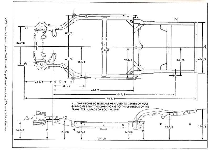
1969 Model specs as per GM manual:
Image


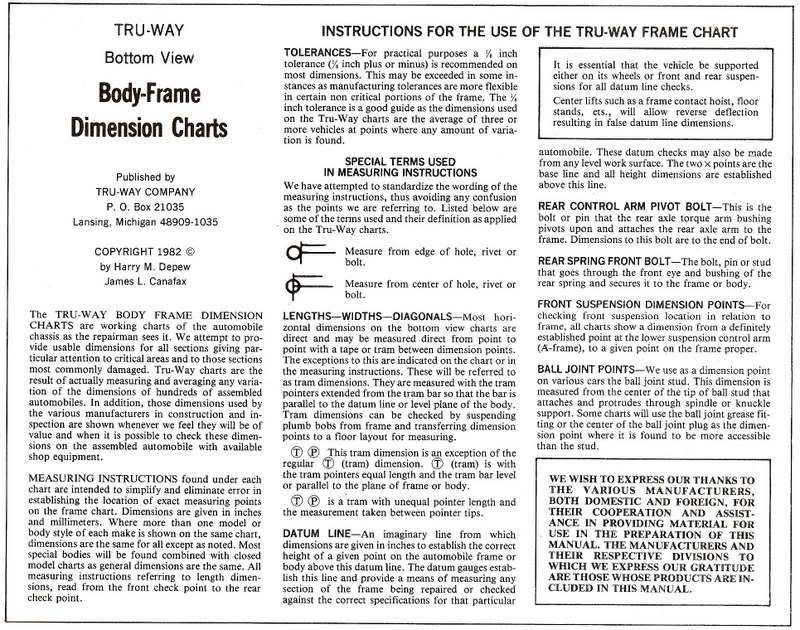
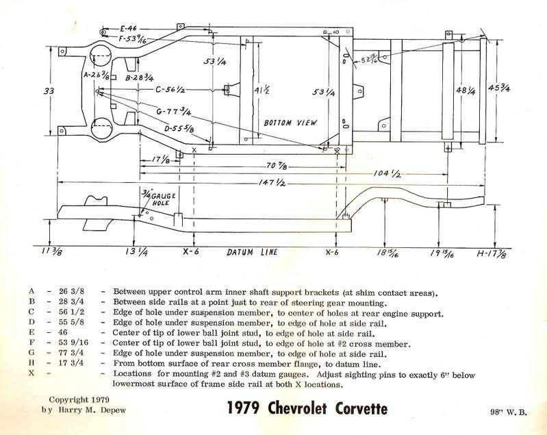
1979 Model specs: (From frame spec book)
Image


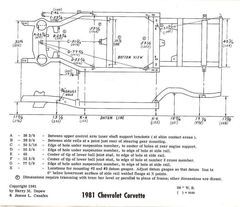
1981 Model specs: (Note how they are not as detailed as prior year, Rrrrrrr!)
Image
 
#2 ·
My only comment is....my '72 OEM printing chebby shop manual for the car line gold and red on page 2-7 frame section shows the vette frame with the exact same as your measures....for your '69....except the front most measure as 14 and 3/8, and the rear most at 23 and 1/2 to the ground....

the rear seems a bit changed, but the front is well within tolerance, I would say...the specs on the plat/layout from on top are the same....

the other elevations are identical....

I have measured my car to those specs listed in my manual...my front is 1.5 inches lo, and the rear is stock height....

:lookinup: should I jack up the rear???

:D
 
#3 ·
:laughing:


As I stated earlier......use this as a guide and not a Blueprint.

Even with the $20,000 Computerized / Laser systems we use today
there are still errors. The most common ones I run into are with "Datum".
I will pull a car to the specs the computer gives me....then I double check
by hanging sheet metal. If the two methods conflict......the sheet metal
always has final-say-so.

If measurements are equal from side to side........meaning one frame horn
is not higher or lower than the other and body gaps are good....leave it alone.

;)
 
#5 ·
#6 · (Edited)
Just a note to those that may not be aware of this.............

If you have a GM shop manual for your given model year this info "should" be in it.
How detailed it will be I can not say............note the '69 example from
a GM manual does not show lower ball joint specs. Where as the Tru-Way
specs do. (They are not shown in my '81 GM manual either.)

Also note that starting in 81 Tru-Way also gave the measurements in Millimeters
as well as Inches.
 
#7 ·
ooooh, very cool. So now in 7 years when I go to have a tube frame made up I'll know where to line up all the body mounts and whatnot. I like it. :partyon:
 
#14 ·
Regarding the '69 frame/drawing, has anyone ever seen any official measurements of the engine mount offset (to the right), and also are the slots in the trans crossmember offset to the right by the same amount as the motor mount horns?

thanks,
Mike
 
#15 ·
hi to all my name is thomas. first thanks for the pics are very good.. i´m studing how to modify a c3 structure....so normal chassis structure how much are strong, you know what´s the limit... maybe a 509 merlin block with 9.5 compression a good th400 and a low traction rear end gear maybe a 3,08 or 3,36....with 550 horsepower and no more than 500 lbs. of torque.... that is a good combination i think to take your vette to the limit , or not? can i put the limit lane more higher without flex or crash my vette structure....?:surprised

thanks to all for your help
 
#20 ·
I had the frame sand blasted then rewelded the seams in places where the factory welds looked weak. There are other things that can be done like welding up the larger holes in the frame but I chose not to do that and leave the frame as-is.
I did cut the middle transmission brace (with the 2 holes for the exhaust) and made a custom removable unit out of 2"x2" x3/8 steel tubing. Richmond 5 spd now fits perfect and plenty of room for any type of exhaust.
In 69, 2 rear braces were added, making the frame stronger.
How strong is the frame, that's a good question. Don't know. Will be running a 540.
Ed
 
#17 ·
Those are Great - and Thanks for posting.
I'm in the midst of a "Frame-Off on my one owner 78", and have all the pieces and parts dissambled, stowed away, etc.
Wonder if anyone has the dimensions I'm looking for in the following image:
http://www.digitalcorvettes.com/forums/attachment.php?attachmentid=1800&stc=1&d=1307132866

Specifically I could use D, d1, and d2. I;m working a splitter/airbox design and wont't be using the other bits.
D is the overall from the leading edge of the main frame member beneath the engine - to the point of the nose ; d1 is the point of the nose back to the trailing edge of the Cylinder (vacuum res); and, d2 is that edge to the LE of the main frame member.

Thanks heaps!
Cheers - Jim
 

Attachments